
Prowler V6-3.5L VIN G (1999)
Drive/Propeller Shaft: Description and Operation
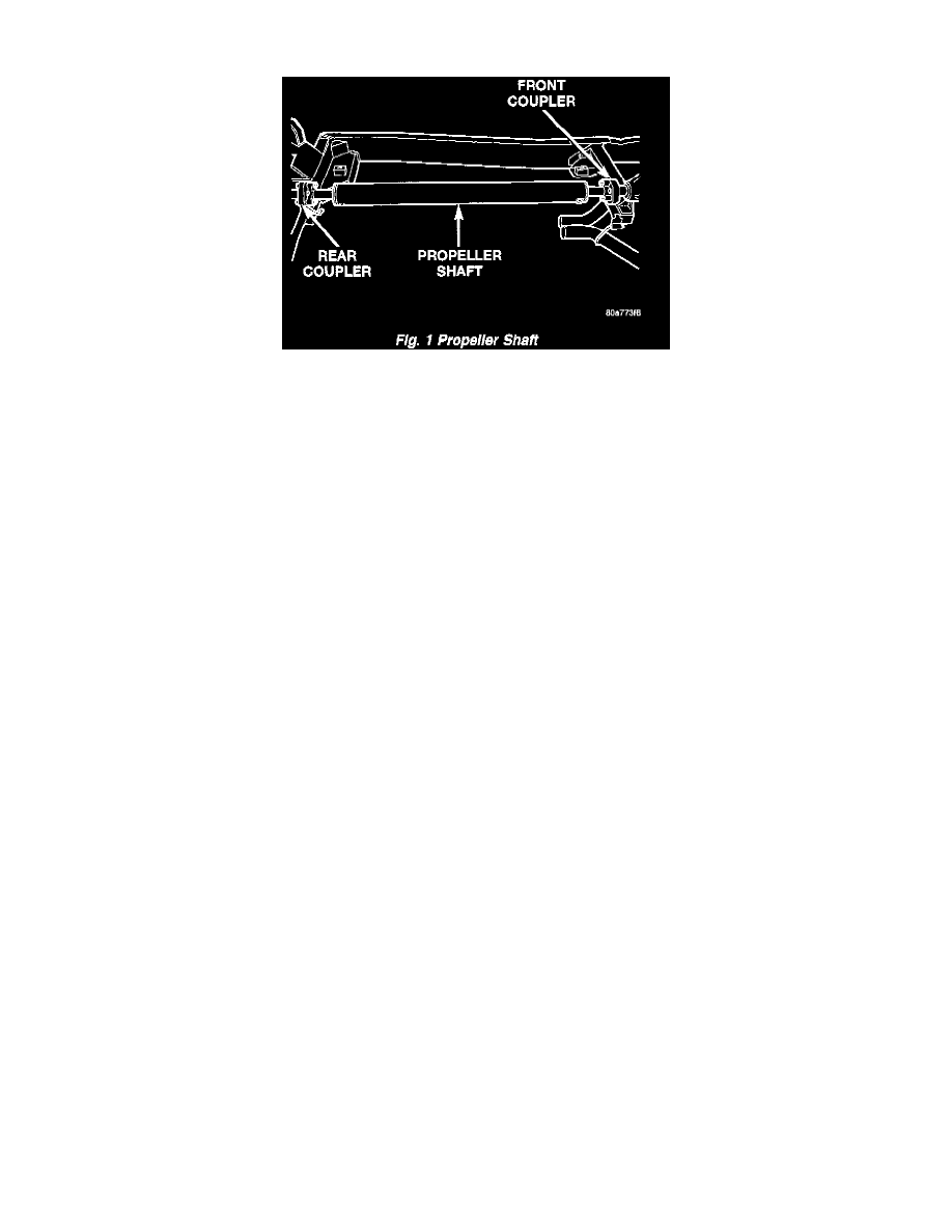
Fig. 1
The propeller shaft is an all aluminum one piece shaft. It uses flexible rubber couplers at each end that attach to the drive flanges. Alignment bushings
are pressed in at each end to positively align the propshaft to the drive Ranges.
NOTE: The propeller shaft and rubber couplers are serviced as an assembly. Do not try to repair any component of the propeller shaft.
The propeller shaft is balanced by the manufacturer to prevent vibration. Before undercoating a vehicle, the propeller shaft and the rubber coupling
flanges should be covered. This will prevent the undercoating from causing an unbalanced condition and vibration.
Use exact replacement hardware for attaching the propeller shaft. Exact replacement with original MOPAR parts will ensure safe operation. The
specified torque must always be applied when tightening any fasteners.
CAUTION: Do not tilt the propeller shaft down or upward at either end. Damage to the internal bushings will result. Do not allow the propeller shaft
to drop or hang from coupling flanges during removal.
CAUTION: It is very important to protect the external surface of the coupling flanges from damage after propeller shaft removal.
CAUTION: If removal of the propeller shaft is necessary, mark the rubber couplers at the front and rear flanges for installation reference. Deattach
the couplers from the flanges only. Do not deattach couplers at the propeller shaft.