
Turismo L4-105 1720cc 1.7L VIN B 2-bbl (1983)
Connecting Rod: Service and Repair
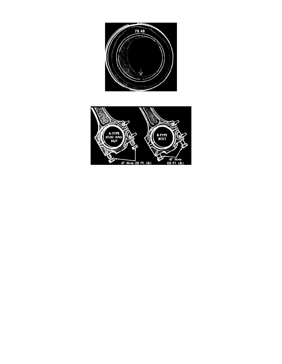
Fig. 11 Piston identification markings
Fig. 12 Connecting rod assemblies
When installing piston and connecting rod assembly the arrow on top of piston must face toward front of engine, Fig. 11, and forged mark on connecting
rod must face toward intermediate shaft, Fig. 12.
Connecting rod side clearance should be .015 inch maximum.
There are two types of connecting rod assemblies. One uses a stud and nut to retain bearing cap and the other uses a bolt to retain bearing cap,
Fig. 12.