
Voyager L4-2.4L VIN B (1997)
Camshaft Position Sensor: Description and Operation
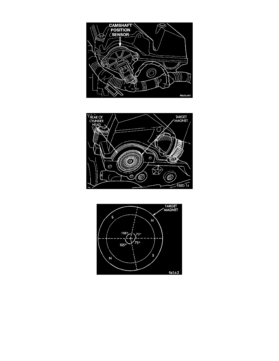
Fig 2 Camshaft Position Sensor
Fig 3 Target Magnet
Fig 4 Target Magnet Polarity
PURPOSE
The PCM determines fuel injection synchronization and cylinder identification from inputs provided by the camshaft position sensor and
crankshaft position sensor. From the two inputs, the PCM determines crankshaft position.
OPERATION
The camshaft position sensor attaches to the rear of the cylinder head (Fig. 2). A target magnet attaches to the rear of the camshaft and indexes to
the correct position (Fig. 3). The target magnet has four different poles arranged in an asymmetrical pattern. As the target magnet rotates, the
camshaft position sensor senses the change in polarity (Fig. 4). The sensor output switch switches from high (5.0 volts) to low (0.30 volts) as the
target magnet rotates. When the north pole of the target magnet passes under the sensor, the output switches high. The sensor output switches low
when the south pole of the target magnet passes underneath.