
Voyager AWD V6-201 3.3L (1992)
PARTS REQUIRED:
As Required
Relay
4728987
As Required
Board, Printed Circuit (MPH w/o Tach, cluster 4728413)
4728611
As Required
Board, Printed Circuit (MPH with Tach, cluster 4728418)
4728610
BODY CONTROLLERS ARE SERVICE CENTER EXCHANGE PARTS. CONTACT YOUR LOCAL HUNTSVILLE FEATURE PRODUCT
SERVICE CENTER TO ORDER AN EXCHANGE BODY CONTROLLER.
As Required
Controller, Body (W/ Mechanical Cluster)
4728591
As Required
Controller, Body (W/ Electronic Cluster)
4728597
REPAIR PROCEDURE 1:
This procedure involves replacing the instrument cluster printed circuit board.
1.
Replace the instrument cluster printed circuit board as outlined on page 8E-6 of the 1992 Front Wheel Drive/All Wheel Drive Van/Wagon Service
Manual (Publication No. 81-370-2105).
2.
Verify that the instrument cluster is now operational.
REPAIR PROCEDURE 2:
This procedure involves replacing the relays or the body controller as necessary.
1.
Remove the lower steering column cover to gain access to the relay bank and the body controller.
2.
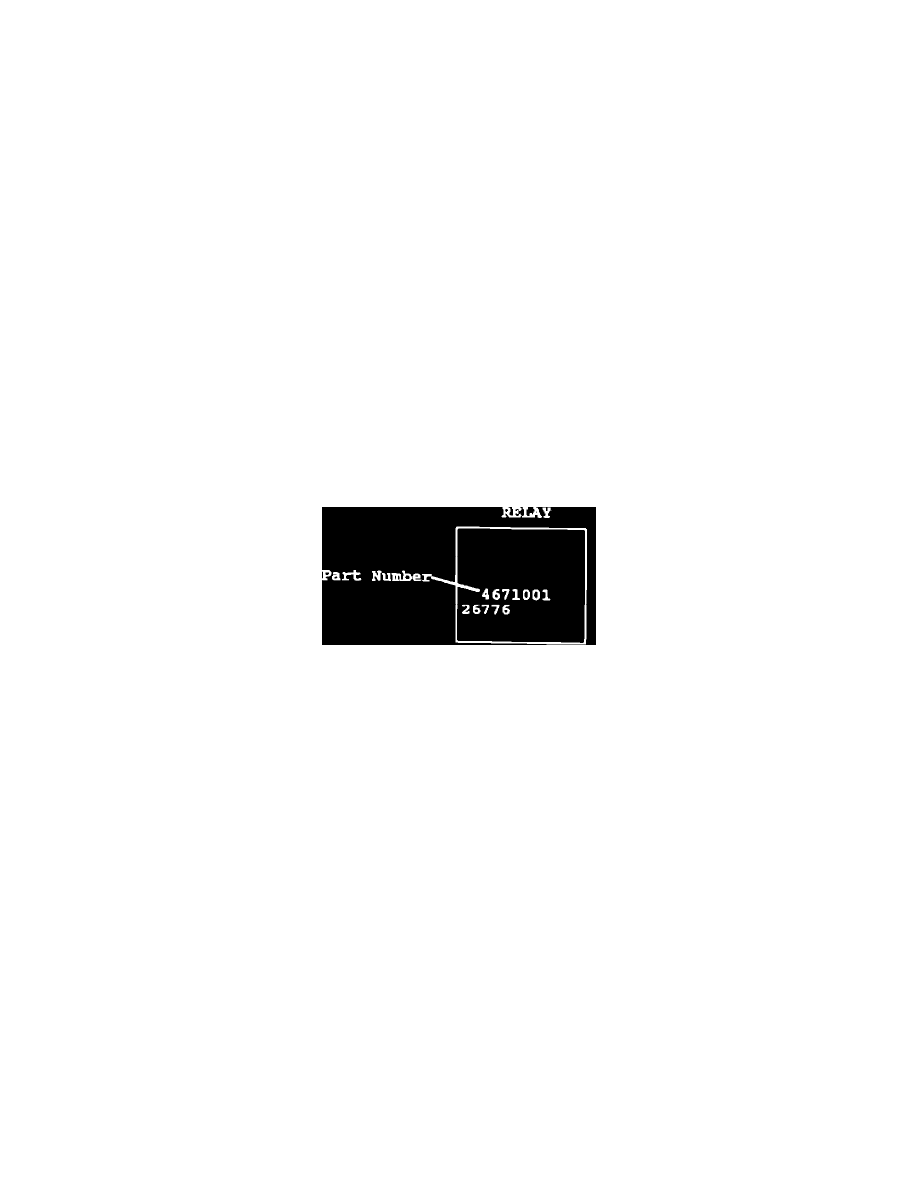
Inspect all relays (up to eight) for part number PN 4671001. Replace all suspect relays with PN 4728987.
3.
If one or both of the following conditions exist, replace the body controller with an exchange unit, as outlined on page 8E-16 of the 1992 Front
Wheel Drive/All Wheel Drive Van/Wagon Service Manual (Publication No. 81-370-2105).
A.
No relays with PN 4671001 found.
B.
The customer reports getting a static electricity shock (ESD) from the vehicle. (Replacing the body controller will eliminate the body
controller lock up condition. A new body controller will not eliminate the ESD condition which is found on many types of vehicles and is
considered normal.)
4.
Verify that all body controller functions are operating. These functions include instrument cluster gauges, chimes, intermittent wipers, power door
locks, illuminated entry, instrument panel illumination, and warning lamps.
5.
Disconnect and reconnect the battery negative cable.
6.
Using the DRB 11 enter the Body Controller Menu and select "READ FAULTS". Check for any body controller diagnostic trouble codes (fault
codes).
7.
If the DRB 11 reads "EEPROM CHECKSUM ERROR", replace the body controller with an exchange unit. Reference the 1992 Body Diagnostics
Procedure Manual (Publication No. 81-699-0244) for any other diagnostic trouble codes.
8.
If the DRB 11 reads "NO FAULTS DETECTED", the repair procedure is complete.
POLICY:
Reimbursable within the provisions of the warranty.