
Voyager AWD V6-201 3.3L (1992)
Wiper Switch: Testing and Inspection
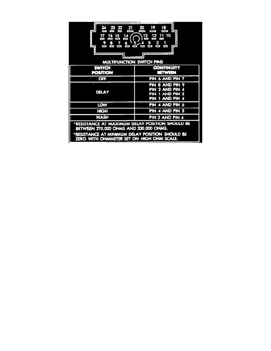
Fig. 16 Intermittent Wiper Pod Switch
1. Place pod switch in the Off position.
2. Check for continuity between terminals A6 and A4. If continuity is not indicated, replace switch.
3. Place pod switch in the Max Delay position (left end of variable resistor).
4. Check for continuity between terminal A7 and terminals A5, A3 and B3. If continuity is not indicated, replace pod switch.
5. Check resistance between terminals A1 and B3. Resistance should measure 210,000-390,000 ohms. If not, replace the pod switch.
6. Place switch in the Min Delay position (right end of variable resistor).
7. Check for continuity between terminal A7 and terminals A5, A3 and B3.
8. Check resistance between terminals A1 and B3. Resistance should measure 350-650 ohms.
9. When the slide is moved from Max to Min Delay, or opposite. Continuity between terminal A7 and terminals A5, A3 and B3 should remain
constant. If not, replace switch.
10.
Resistance between terminals A1 and B3 will decrease as the control is moved from Max to Min Delay, or increase when moved from Min to Max
Delay. If not, replace switch.
11.
Place switch in the Lo position, then check for continuity between terminals A4 and B3. If continuity is not indicated, replace pod switch.
12.
Place switch in Hi position, then check for continuity between terminals A2 and B3. If continuity is not indicated, replace switch.
13.
Check for continuity between terminals B3 and B4, when the front washer button is depressed. If not, replace switch.
14.
Check for continuity between terminals B2 and B5 when the rear wiper switch is in the On position (indicator lamp will illuminate only when the
headlamps are on). If continuity is not indicated, replace switch.
15.
Check continuity between terminals B1 and B5 when the rear washer button is depressed. If continuity is not indicated, replace the switch.
16.
Two switch illuminating bulbs are fed by terminal B5 (ground) and B6 (power).