
6000 V6-173 2.8L (1988)
A/C Signal: Description and Operation
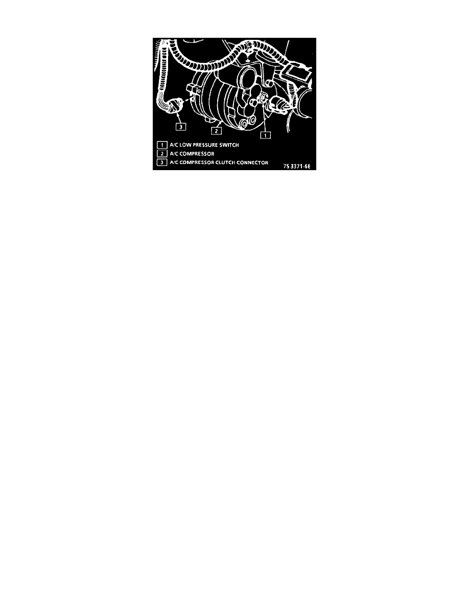
A/C Low Pressure Switch
PURPOSE
In order to improve idle quality and wide open throttle performance, the A/C compressor is controlled by the Electronic Control Module (ECM).
There are two different types of A/C systems used in GM vehicles. One is referred to as C.C.O.T. (Cycling Clutch Orifice Tube), which uses a
fixed displacement compressor. The other type of system uses a compressor with a variable displacement and is referred to as the V-5 type system.
The V-5 type meets A/C requirements without cycling. For descriptions of both types, and an explanation of the components used, refer to
Heating and Air Conditioning.
OPERATION
This system consists of a low pressure switch, a high pressure cut-out switch, a control relay, and the compressor. An A/C fan control pressure
switch is also used with A/C equipped vehicles, to tell the ECM to turn "ON" the cooling fan when A/C head pressure is high. This switch opens
when A/C pressure exceeds about 1380 kPa (200 psi).
The low pressure switch, mounted in the compressor, is closed when the system contains a sufficient refrigerant charge. This switch opens, when
pressure is less than about 276 kPa (40 psi).
The high pressure cut-out switch (normally closed) opens when head pressure gets too high. This disables the A/C clutch, before damage can occur
to the system. This switch opens when pressure is greater than about 3034 kPa (440 psi).
The A/C control relay is controlled by the ECM, so that the ECM can increase idle speed before turning "ON" the clutch, to disable the clutch
during wide open throttle or during high power steering loads. Refer to System Diagnosis / Diagnostic Charts / Chart C-10B for specific wiring
and circuit description.