
Bonneville V6-3800 3.8L (1991)
Wiring Diagram
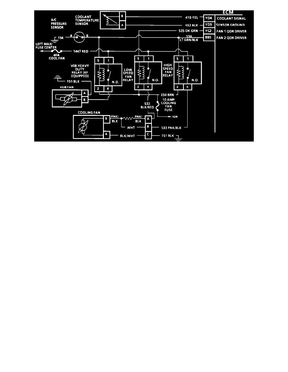
CIRCUIT DESCRIPTION:
Power for the fan motor comes through the fusible link to terminal "1" on all relays. The relays are energized when current flows to ground through the
ECM (quad-drivers).
Low Speed Relay - The ECM energizes the relay through terminal "YC2" when the coolant temperature reaches 101°C (214°F). As long as the ignition
remains in the "ON" position the coolant fan will continue to run until the coolant temperature falls below 99°C (210°F). The low speed fan will also run
any time the A/C is requested.
High Speed Relay - The high speed relay is energized by the ECM or the A/C pressure switch. If the A/C refrigerant pressure reaches 275 psi (1896 kPa)
or the coolant temperature reaches 108°C (226°F), the high speed fan relay is energized.
NOTE: Because of all the possible color code combinations used on electrical wiring diagrams, always refer to SCHEMATIC
DIAGRAMS/ELECTRICAL AND ELECTRONIC WIRING DIAGRAMS/ECM CONNECTOR IDENTIFICATION for correct color code
identification of circuit.
TEST DESCRIPTION: Numbers below refer to circled numbers on the diagnostic chart.
1.
Checks to see if CKT 535 is shorted to ground, which would keep the relay closed at all times.
2.
Checks to see if CKT 536 is shorted to ground. A light indicates the wire is shorted to ground the following steps will isolate the short.
3.
If the test light is "OFF," after disconnecting the ECM, be sure circuit 535 is not shorted to B+. If not shorted to B+, the ECM is shorted
internally.
4.
If the test light is "OFF" after disconnecting the ECM, be sure circuit 536 is not shorted to B+. If not shorted to B+, the ECM is shorted
internally.
Part 3 of 4