
Firebird V8-305 5.0L (1982)
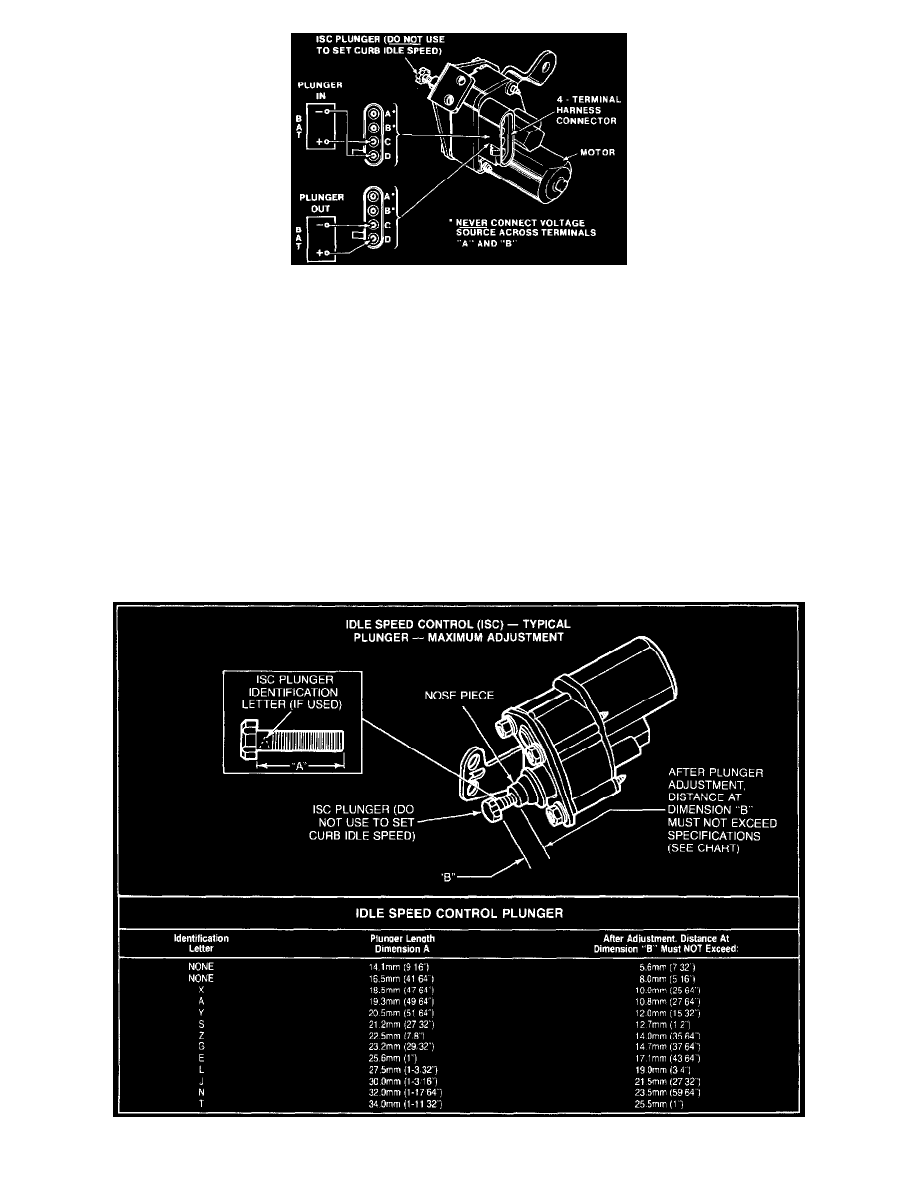
Fig. 132 Idle Speed Control (ISC) Test Connections
4. Using a jumper wire, connect battery voltage to terminal "C" on ISC motor--Fig 132--then connect a jumper wire between terminal "D" and
ground.
NOTE: Do not leave battery voltage connected to ISC motor longer than necessary to retract solenoid plunger. Do not connect battery voltage to
terminals "A" or "B" on motor. ISC motor will be damaged if connections are improperly made.
5. Start engine and run until dwell reading begins to fluctuate. Place transmission in drive (manual transmission in neutral).
6. With ISC plunger fully retracted, adjust idle speed to specified minimum authority RPM with throttle stop screw.
7. Place transmission in neutral and reverse jumper wire connections. Connect battery voltage to terminal "D", and connect terminal "C" to ground.
NOTE: Leave jumper wires connected only long enough to fully extend ISC plunger.
8. With plunger fully extended, adjust idle speed to specified maximum authority RPM (manual transmission), or 1500 RPM (automatic
transmission), by turning ISC plunger with tool J-29607 or equivalent.
9. Place automatic transmission in drive and adjust idle speed to specified maximum authority RPM with ISC plunger.
10. Reconnect jumper wires as in step 7 and recheck maximum authority RPM. Motor will ratchet at full extension with voltage applied.
Fig. 131 Idle Speed Control (ISC) Plunger Specifications