Firebird V8-350 5.7L VIN P SFI (1996)

Accessory Delay Module: Diagram Information and Instructions
Abbreviation
A/C
Air Conditioning
CCM
Central Control Module
CKT
Circuit
CONN
Connector
EBCM
Electronic Brake Control Module
EBTCM
Electronic Brake and Traction Control Module
ECM
Engine Control Module
HARN
Harness
I/P
Instrument Panel
LH
Left Hand
PCM
Powertrain Control Module
RH
Right Hand
TERM
Terminal
Cell References
CELL REFERENCES
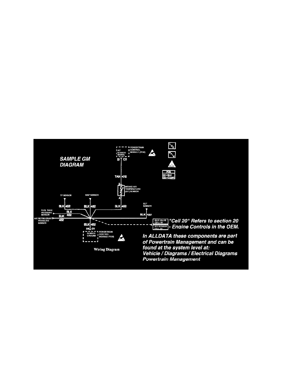
General Motors vehicles often use "CELL" references in their electrical wiring diagrams. These references are used in the Original Equipment
Manual to refer to a section in the manual and not a specific diagram(s).
GM Sample Diagram W/ Cell Reference
For instance, in the diagram illustrated "Cell 20" is not a reference to another diagram but a reference to "Section 20" in the OE manual. In the
example, "Section 20" is the engine control section of the manual.
To navigate through these "Cell" references start at the vehicle level and go to: Diagrams / Electrical Diagrams - for a complete list of the diagrams
available for the vehicle. Choose the system you are working on and view those diagrams.
Note: If unsure of the system - try utilizing the search feature. Type a component in the search feature that belongs to the system and when the
results are displayed note the path displayed. This will show the system the component belongs in.
Electrostatic Discharge (ESD Sensitive Devices)
All Electrostatic Discharge (ESD) sensitive components are Solid State and the following information applies to them.
