
G6 V6-3.6L (2007)
Variable Valve Timing Actuator: Service and Repair
Camshaft Position Actuator Replacement - Bank 2 (Left Side) Exhaust
First Design
CAMSHAFT POSITION ACTUATOR REPLACEMENT - BANK 2 (LEFT SIDE) EXHAUST - FIRST DESIGN
Special Tools: EN 46108 Timing Chain Retention Tool
Important: To identify a camshaft drive design, refer to Camshaft Timing Drive Design Identification. See: Timing Components/Timing Component
Alignment Marks/Locations
Removal Procedure
1. Remove the lower intake manifold. See: Intake Manifold/Service and Repair
2. Remove the left camshaft cover. See: Cylinder Head Assembly/Valve Cover/Service and Repair
3. Remove the left intake and exhaust camshaft position sensors. See: Powertrain Management/Computers and Control Systems/Camshaft Position
Sensor/Service and Repair
4. Remove the left intake and exhaust camshaft position actuator solenoid. See: Actuators and Solenoids - Engine/Variable Valve Timing
Solenoid/Service and Repair
Important: Rotate the crankshaft balancer in a clockwise rotation ONLY.
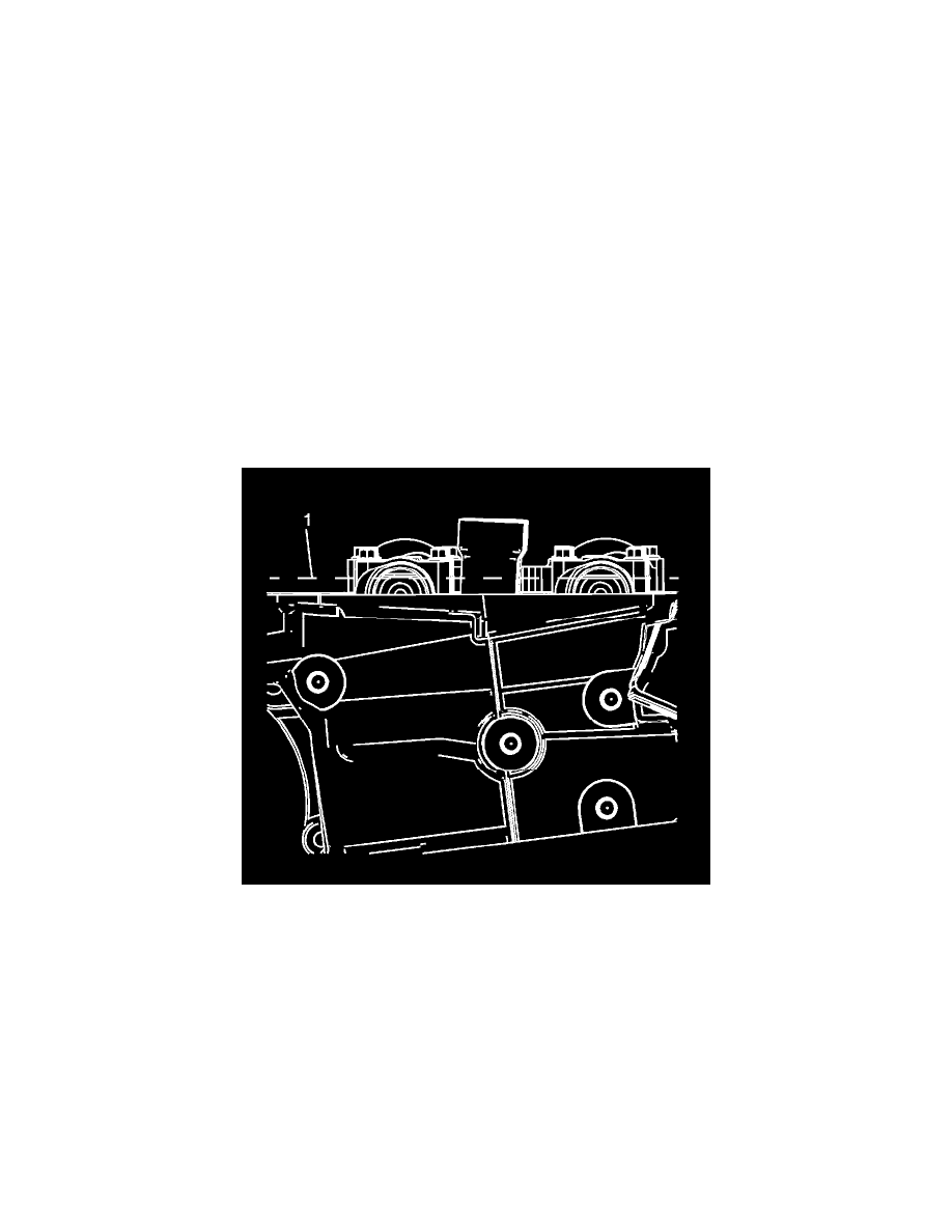
5. Rotate the crankshaft using the crankshaft balancer bolt until the camshafts are in a neutral (low tension) position. The camshaft flats will be
parallel with the camshaft cover rail (1).
Notice: A wrench must be used on the hex of the camshaft when loosening or tightening in order to prevent component damage. Failure to prevent
the torque reaction against the timing drive chain can lead to timing drive chain failure.