
G8 V6-3.6L (2008)
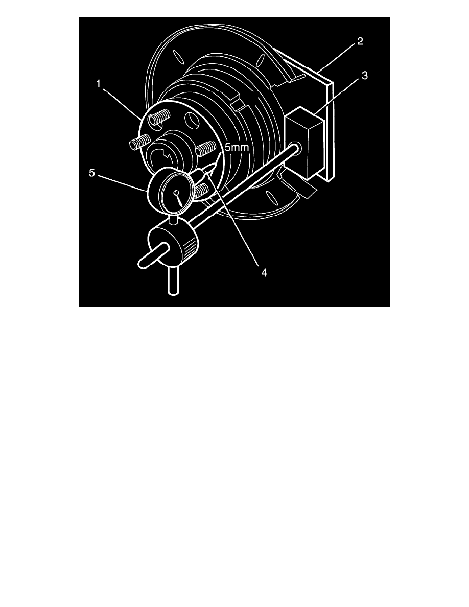
2. Set up a dial indicator (5) on a magnetic base (3) and attach to the pre-fabricated mounting plate (2).
3. Position the pointer (4) on the hub face 5 mm (0.2 in) from the edge of the hub (1).
Important: For this inspection to be performed with 100 percent accuracy, a flat parallel surface plate attached to the hub should be
used. However, measuring runout on the hub face 5 mm (0.2 in) from the edge of the hub (1) should yield adequate results.
Important: The number of divisions between the points of minimum and maximum runout on the dial indicator (5) is the total indicated
runout.
4. Rotate the hub by the wheel studs and note the points of minimum and maximum runout on the dial indicator (5).
5. If the runout measured in Step 3 exceeds 0.025 mm (25 micron), replace the hub assembly.
Maximum hub total indicated runout (TIR): 0.25 mm