
Grand Prix V6-191 3.1L (1989)
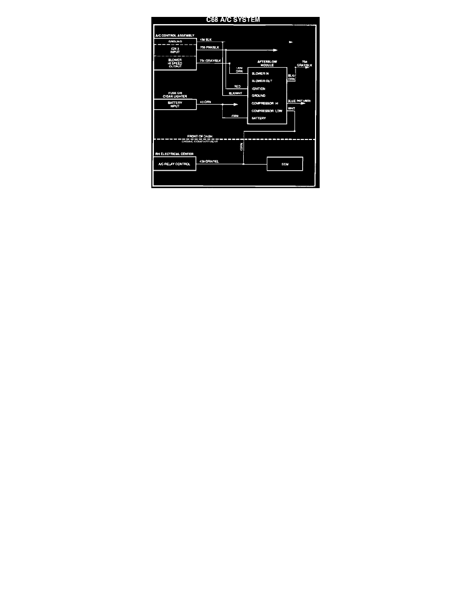
FIGURE 4 - CIRCUIT DIAGRAM
IMPORTANT:
The circuit diagrams, shown in Figures 3 and 4, shows the circuit numbers generally used on the subject model year
vehicles. However, to make sure of the correct circuits and wire colors are spliced into, refer to section 8A of the Service
Manual.
25.
Disconnect the afterblow module from the jumper harness and set the module aside.
26.
C67 A/C SYSTEM: Splice the black/white wire (pin C) of the jumper harness into the black ground wire (circuit # 150) in the black connector
(cavity # 12) of the A/C control assembly wiring.
C68 A/C SYSTEM: Splice the black/white wire (pin C) of the jumper harness into the black ground wire (circuit # 150) in the gray connector
(cavity # 14) of the A/C control assembly wiring.
27.
C67 A/C SYSTEM: Splice the red wire (pin B) of the jumper harness into the pink/black wire (circuit # 750) of the black connector (cavity # 4) of
the A/C control assembly wiring.
C68 A/C SYSTEM: Splice the red wire (pin B) of the jumper harness into the pink/black wire (circuit # 750) of the black connector (cavity #
12) of the A/C control assembly wiring.
28.
C67 A/C SYSTEM: Cut the orange blower Hi speed out put wire (circuit # 52) of the black blower switch connector of the A/C control assembly
wiring. Splice the tan/orange wire (pin F) of the jumper harness to the orange wire from the A/C control assembly. Splice the black/orange wire
(pin G) of the jumper harness to the other end of the orange wire.
C68 A/C SYSTEM: Cut the gray/black wire (circuit # 754) of the white connector (cavity # 15) of the A/C control assembly wiring. Splice the
tan/orange wire (pin F) of the jumper harness to the gray/black wire from the A/C control assembly. Splice the black/orange wire (pin G) of the
jumper harness to the other end of the gray/black wire.
THE NEXT THREE STEPS ARE THE SAME FOR BOTH THE C67 AND C68 SYSTEMS
29.
Splice the orange wire (pin A) of the jumper harness into the battery feed wire (circuit # 40) at the fuse block or the cigar lighter.
30.
Splice the end of the green wire, that is routed to the engine compartment to the white wire (Pin E) of the jumper harness.
31.
In the engine compartment, splice the green wire into the green/yellow (Circuit # 459) at either the A/C compressor relay (Cavity # 1) of the R.H.
electrical center or the ECM (Cavity A12).
32.
Connect the negative battery cable.
33.
Test the afterblow module, per the following procedure.
34.
Cut off the bare end of the blue wire (Pin D) of the jumper harness, tape the end and fold and tape wire to the harness.
35.
Mount the afterblow module in a convenient location under the dash using foam insulation as necessary to ensure a rattle-free installation of the
module.
36.
Install the secondary dash panel, the splash shields and return engine to its proper position.