
Trans Sport V6-191 3.1L (1990)
Headlamp Dimmer Switch: Service and Repair
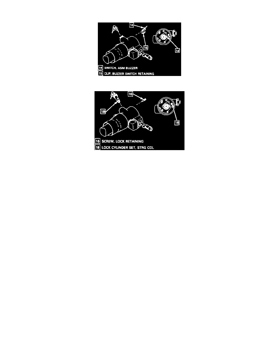
Fig. 6 Ignition Key Alarm/buzzer Assembly Removal
Fig. 7 Ignition Key Lock Cylinder Removal
1.
Refer to steps 1 through 9 in TURN SIGNAL SWITCH.
2.
Remove key lock cylinder set, then remove alarm/buzzer assembly and clip, Fig. 6.
3.
Reinsert key in lock cylinder and turn key to the LOCK position.
4.
Remove lock retaining screws and lock cylinder, Fig. 7.
5.
Reverse procedure to install, noting that key is in the RUN position when installing alarm/buzzer assembly.
6.
On models with cruise control, remove housing cover end cap, then unplug connector and gently pull harness through bowl assembly, housing
and cover assembly. Remove multi-function lever.
7.
On all models, remove lock housing cover screws and lock housing cover assembly.
8.
Remove tilt lever, then column housing cover end cap and dimmer switch rod actuator.
9.
Gently pull pivot switch wire harness through bowl assembly and column housing.
10.
Remove switch actuator pivot pin, pivot and pulse switch assembly
11.
Remove wheel tilt spring retainer, wheel tilt spring and spring guide
12.
Using puller tool No. J 21854-91 remove pivot pin, then reinstall tilt lever.
13.
Remove column housing by pulling back on the tilt lever, then pull housing down and away from column.
14.
Remove release lever pin, then shoe release lever and release lever spring.
15.
Remove dowel pin, lock shoes and shoe springs from column housing.
16.
Remove bearing assembly, hex head screw, lock bolt spring and lock bolt from column housing.
17.
Remove column from vehicle. Once steering column is removed from vehicle, the column is extremely susceptible to damage. Dropping
column on its end could collapse steering shaft or loosen plastic injections which maintain column rigidity. Do not lean on column and
under no circumstances should a hammer be used on ends of column. Any damage to the column could impair the columns collapsible
design.
18.
Remove bearing and seal retainer.
19.
Remove lower spring retainer, lower bearing spring and lower bearing seat.
20.
Remove hex head screws, then adapter and bearing assembly.
21.
Mark both lower column and upper column shafts for assembly reference. Failure to mark shafts may cause the steering wheel to be turned 180°.