
Vibe L4-1.8L VIN L (2003)
Steps 15-17
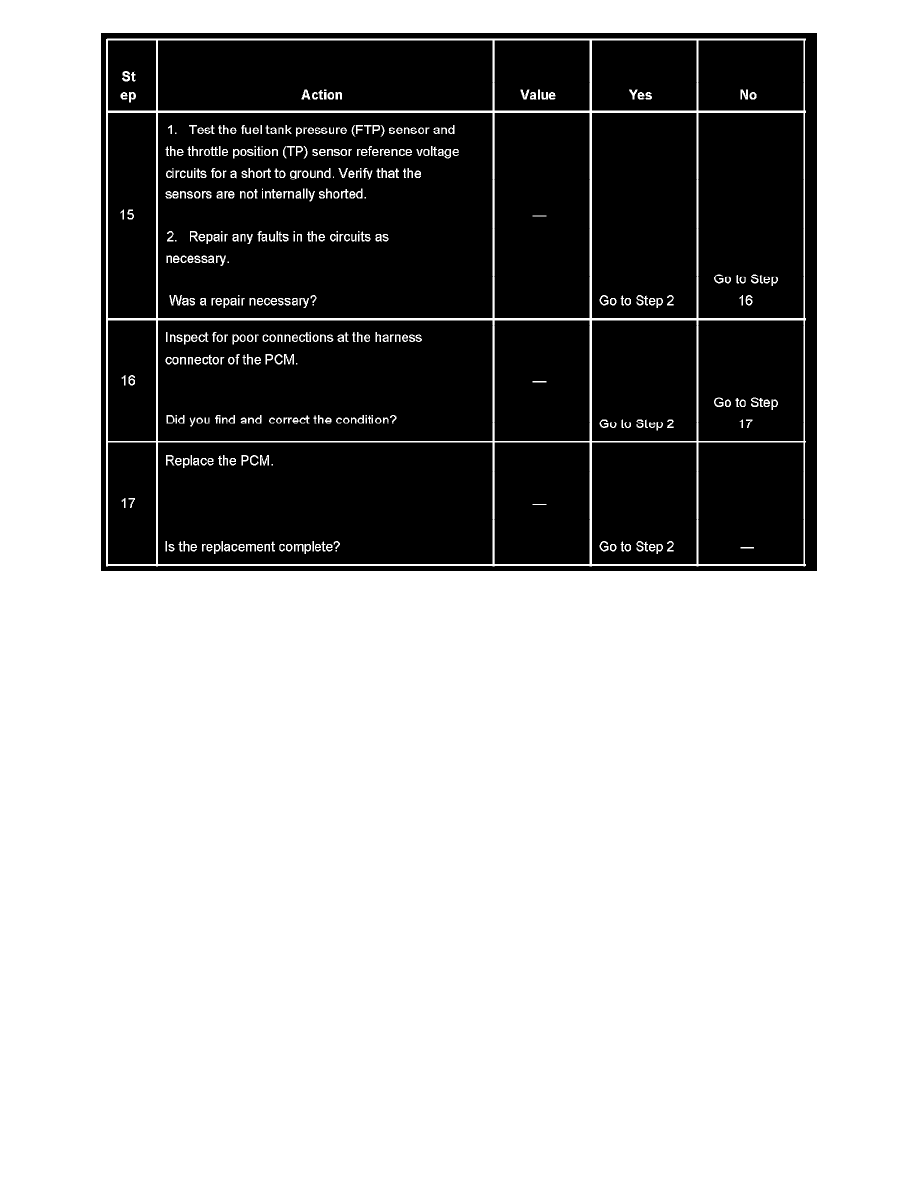
The numbers below refer to the step numbers on the diagnostic table.
3. This step checks whether the scan tool can communicate with other control modules on the vehicle. If the scan tool can communicate with one of
the other modules then the DLC connector, the shared circuits, and the scan tool are OK.
5. The modules supply a low current (about 1.85 mA) voltage on the serial data circuit. The normal circuit low current will NOT illuminate a test
lamp. If the circuit is shorted to battery positive the higher current will illuminate the test lamp.
7. This step checks whether the PCM is receiving ignition positive voltage from the EFI relay when the ignition is ON. The PCM cannot provide
serial data without ignition positive voltage from the EFI relay.
8. If the engine starts and runs, the EFI relay is OK.
9. The PCM cannot provide serial data without the correct power and grounds.
13. The scan tool may be damaged by high current flow on the serial data circuit at DLC terminal 7. Inspect the scan tool for proper operation on a
known good vehicle that uses terminal 7 of the DLC for serial data communication.
15. A shorted sensor reference voltage circuit can cause a loss of scan tool communication with the PCM.
Scan Tool Does Not Power Up
SCAN TOOL DOES NOT POWER UP
CIRCUIT DESCRIPTION
The data link connector (DLC) provides operating power for the scan tool at terminal 16 (battery positive voltage) and at terminal 4 (ground). The
DLC provides the class 2 serial data signals at terminal 7. The scan tool will power up with the ignition OFF. Many modules, however, will not
communicate unless the DIM detects that the ignition is ON and sends the appropriate power mode message.
TEST DESCRIPTION