
Vibe AWD L4-2.4L (2009)
(Except All Wheel Drive and GT) (See: Brake Caliper/Service and Repair/Removal and Replacement/Rear Brake Caliper Replacement).
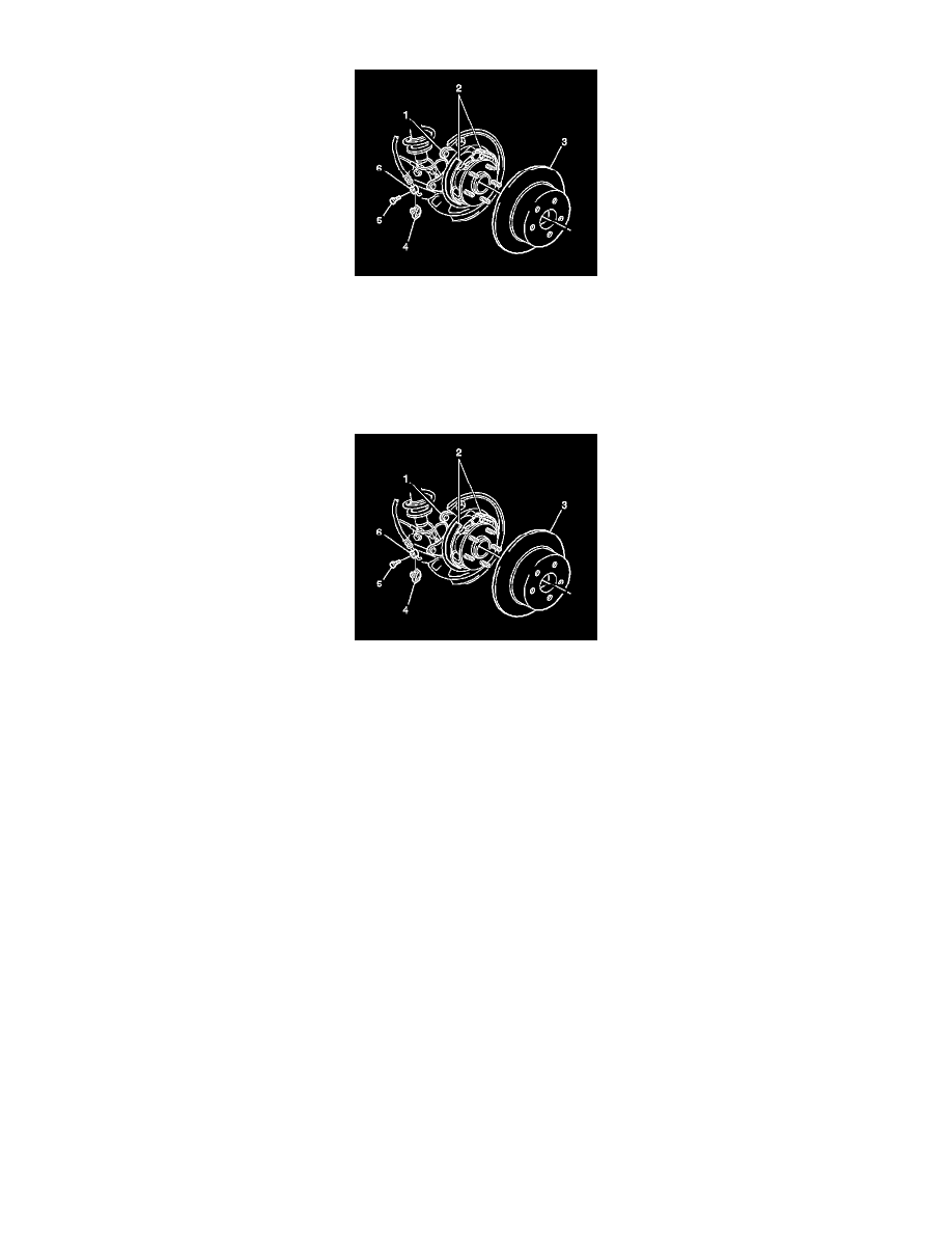
5. Use paint in order to mark the position of the brake rotor (3) to the hub.
6. If the vehicle has a drum-in-hat style park brake system, adjust the park brake in order to move the park brake shoes away from the drum portion
of the rotor. Refer to Parking Brake Adjustment (All Wheel Drive and GT) (See: Parking Brake System/Adjustments)Parking Brake Adjustment
(Except All Wheel Drive and GT) (See: Parking Brake System/Adjustments).
7. Remove the brake rotor.
Installation Procedure
Note: Clean the hub and the brake rotor mating surfaces. Failure to remove corrosion and other contaminants from the hub and the rotor may
result in excessive assembled lateral runout (LRO) of the brake rotor, which could lead to brake pulsation.
1. Using the J-42450-A - kit , thoroughly clean any rust or corrosion from the mating surface of the hub flange.
2. Using the J-41013 - kit , thoroughly clean any rust or corrosion from the mating surface of the hub and the brake rotor (3).
3. Inspect the mating surfaces of the hub and the rotor. Verify that there are no foreign particles or debris remaining.
4. If the vehicle has a drum-in-hat style park brake system, adjust the park brake in order to move the park brake shoes away from the drum portion
of the rotor. Refer to Parking Brake Adjustment (All Wheel Drive and GT) (See: Parking Brake System/Adjustments)Parking Brake Adjustment
(Except All Wheel Drive and GT) (See: Parking Brake System/Adjustments).
5. Install the brake rotor to the hub. If you are installing the old rotor, use the paint mark for proper orientation of the rotor to the flange.
6. If you removed and installed the brake rotor as part of a brake system repair, measure the assembled lateral runout (LRO) of the brake rotor in
order to ensure optimum performance of the disc brakes. Refer to Brake Rotor Assembled Lateral Runout Measurement (See: Testing and
Inspection/Brake Rotor Assembled Lateral Runout Measurement).
7. If the brake rotor assembled LRO measurement exceeds the specification, adjust the LRO to the specification. Refer to Brake Rotor Assembled
Lateral Runout Correction (See: Testing and Inspection/Brake Rotor Assembled Lateral Runout Correction).
8. Install the brake caliper and the pads as an assembly to the suspension knuckle. Refer to Rear Brake Caliper Replacement (All Wheel Drive and
GT) (See: Brake Caliper/Service and Repair/Removal and Replacement/Rear Brake Caliper Replacement)Rear Brake Caliper Replacement
(Except All Wheel Drive and GT) (See: Brake Caliper/Service and Repair/Removal and Replacement/Rear Brake Caliper Replacement).
9. Install the tire and wheel assembly. Refer to Tire and Wheel Removal and Installation (See: Maintenance/Wheels and Tires/Service and Repair).
10. Lower the vehicle.
11. Adjust the park brake. Refer to Parking Brake Adjustment (All Wheel Drive and GT) (See: Parking Brake System/Adjustments)Parking Brake
Adjustment (Except All Wheel Drive and GT) (See: Parking Brake System/Adjustments).
12. If you installed new pads or a new rotor, burnish the pads and rotors. Refer to Brake Pad and Rotor Burnishing (See: Brake Pad/Service and
Repair/Brake Pad and Rotor Burnishing).