911 Carrera 2 Cabriolet F6-3600cc 3.6L SOHC (1992)

Acceleration Enrichment Module: Diagram Information and Instructions
How to Use Diagrams
Diagrams By Coordinates
To locate the diagram section containing a coordinate of a continued circuit, refer to Diagrams By Coordinates, located at Vehicle Diagrams. See:
Diagrams/Electrical Diagrams/Diagrams By Coordinates
Diagram Sections, Fields and Wire Continuations
Porsche wiring diagrams are separated into diagram sections and use a coordinate system which divides each section into small fields. Letter
coordinates span across the top and bottom of each diagram section and numeric coordinates span down each side of the diagram section.
Since wiring often continues from one diagram section to a different diagram section, the coordinates and, in some cases, the terminal designations
are specified. To follow a circuit that continues to a new diagram section, determine the color and size of the wire, identify the new alpha-numeric
coordinate, and go to the field coordinate of the new diagram section. Note that there may be more than one circuit that is continued to this field
and you will need the field coordinate from which the circuit was continued and the color code of the wire to identify the correct circuit.
The ground points are identified with "GP" (Ground points may be identified with "MP" prior to 1991 model year).
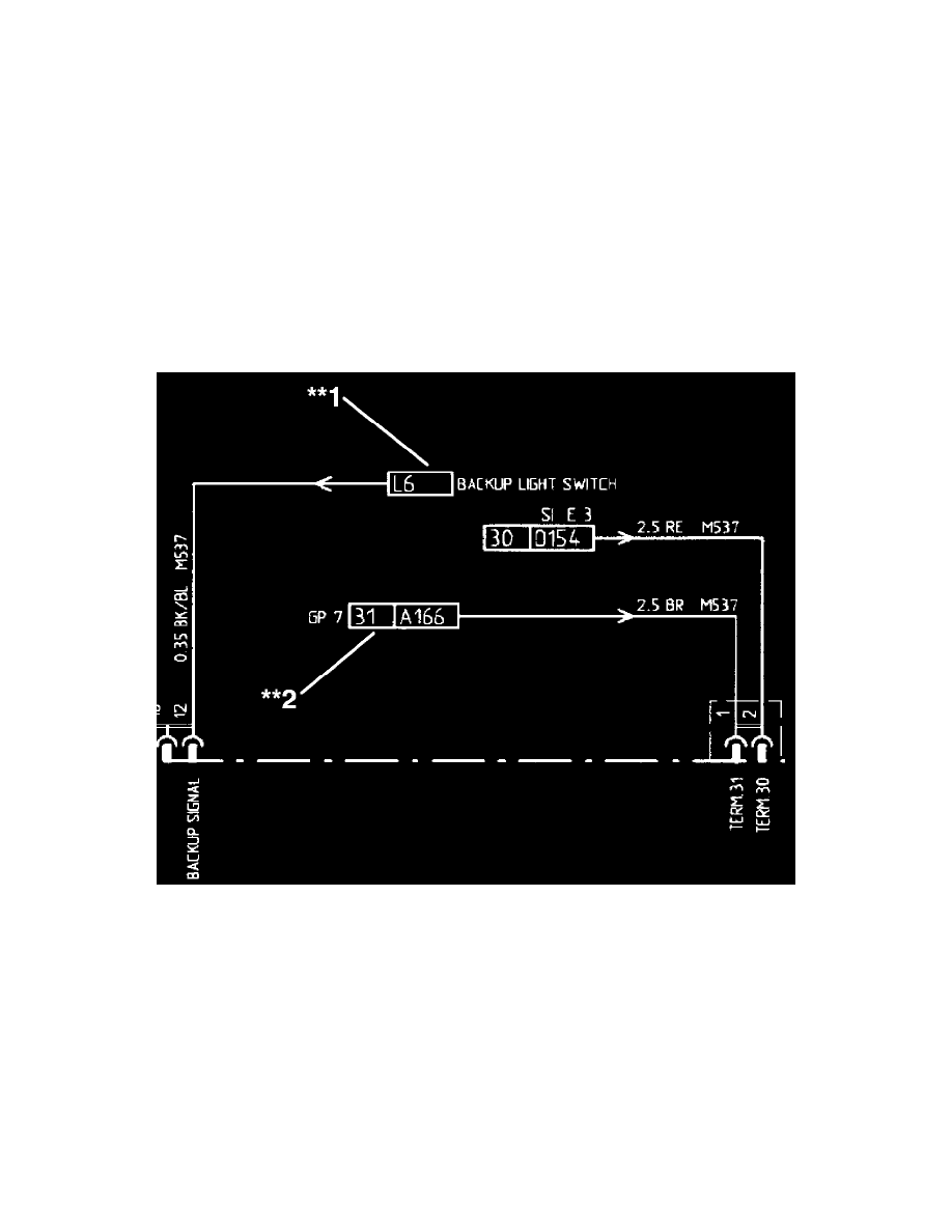
Example:
Note**1 Wire coming in (Continuation) from Backup Light Switch, at coordinate location L6.
Note**2 Wire coming in (Continuation) from Ground Point 7, at coordinate location A166. Terminal ID is 31.
