
911 Carrera Coupe F6-3600cc 3.6L SOHC (1997)
Alarm Module: Diagrams
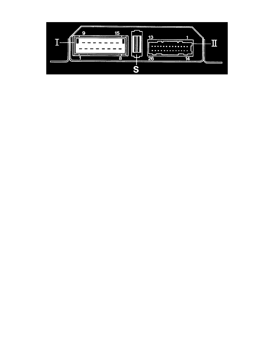
Connector I
Terminal:
1 - terminal 30
2 - terminal 31 (ground)
3 - terminal 30 (flashers)
4 - Anti-drive-off feature (to DME control unit)
6 - terminal 15 (from airbag control unit)
7 - Interior light
8 - Left-hand turn signal
9 - Right-hand turn signal
10 - Alarm horn
11 - Motor "closed", door locking motor
12 - Motor "open", door locking motor
14 - Alarm readiness lamp, driver's door
15 - Alarm readiness lamp, passenger's door
S
- fuse
Connector II
Terminal:
1 - Activate / closed
2 - Deactivate / open
3 - Luggage compartment contact
5 - Rear lid contact
6 - Speedo signal terminal A
7 - Input 1, rear parcel shelf switch for M 419
8 - Input 2
9 - Radio alarm contact
10 - Central Locking System position switch "open"
11 - Central Locking System button
12 - Central Locking System position switch "closed"
13 - Radio 1 (ground across alarm horn)
14 - Diagnosis "L"
15 - Diagnosis "K"
16 - Glove box contact
17 - Input 3
18 - terminal 15
20 - Central Locking System warning lamp
21 - Door contacts
23 - terminal 61
24 - External electronics