
911 Carrera Coupe F6-3600cc 3.6L SOHC (1997)
Input Shaft Removal/Installation (Part 5 Of 5)
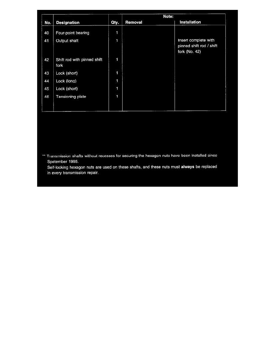
Removal Notes
NOTE: Parts No. 1 to 30 are removed with the tensioning plate remaining fitted.
Installation Notes
1. Using a suitable flat iron bar, clamp tensioning plate in a vise in such a manner that the hole for the shift rod locks is horizontal.
2. Check synchromesh of 1st and 2nd gears.
-
To do so, place friction ring, tapered ring and synchronizing ring in correct position onto gearwheel.
-
Check gap "A" with a feeler gauge.
Old design installation dimension:
New: 1.3 to 1.95 mm
Wear dimension: 1.0 mm
New design, installation dimension:
New: 1.5 to 2.0 mm
Wear dimension: 1.2 mm (see below)
3. Observe installation position of locks.
NOTE:
-
After fitting the shift rods, do not move them across the neutral or gear latch positions as this may cause the small intermediate locks to drop
out inadvertently.
-
To avoid inadvertent movement of the shift rods, lock shift rods by engaging 4th gear.
Modified Synchromesh On 1st And 2nd Gear
-
The following parts have been modified from transmission No.:
G 5020 1 000 884
G 5020 2 000 883
G 5021 1 002 186
G 5021 2 001 230