
944 S L4-2479cc 2.5L DOHC (1987)
Engine Control Module: Connector Views
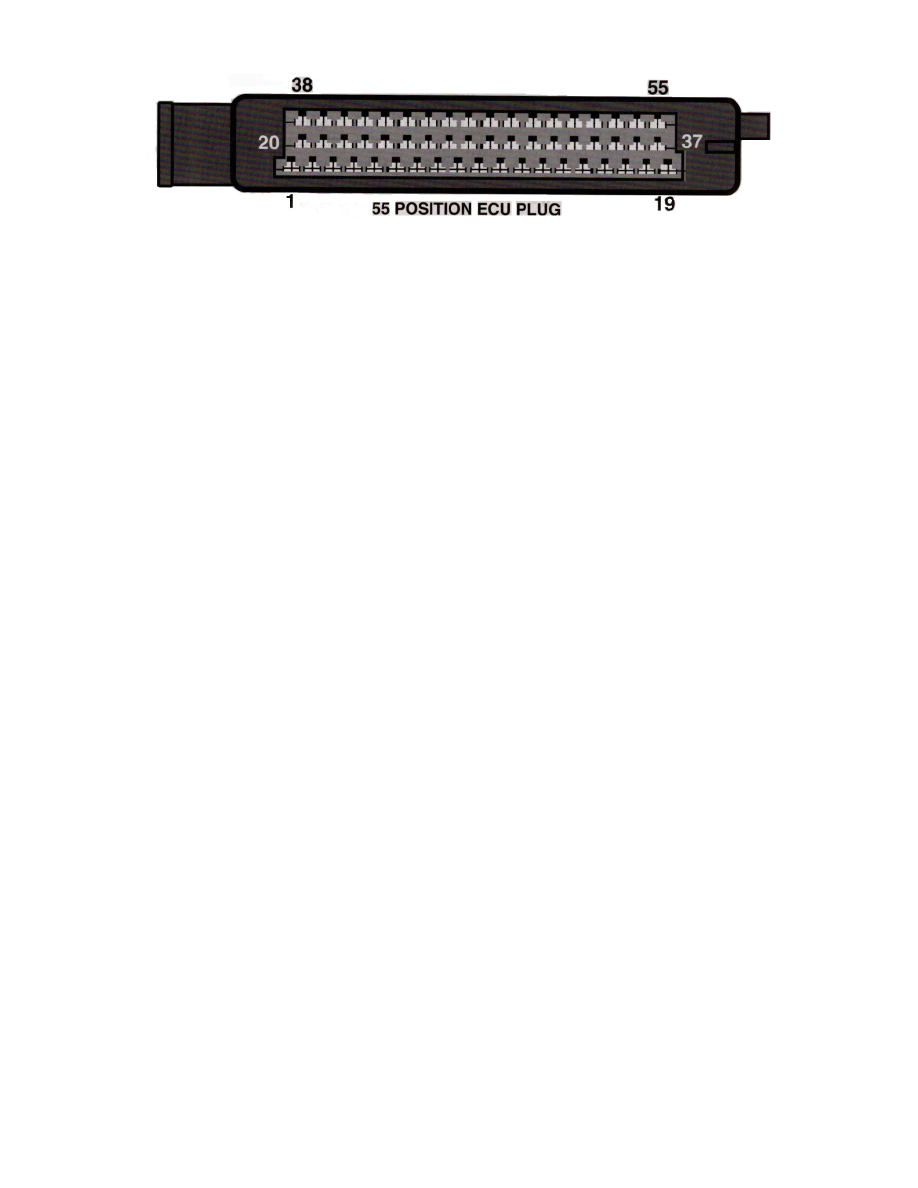
Pin Layout
System
DME
Location
- Under drivers seat
Terminal ID
1 - Timing control (Blk)
2 - Ground (Brn)
3 - Fuel pump relay control (Brn/Grn)
4 - Idle speed control valve (Wht/yel)
5 - Evaporative purge solenoid (Brn)
6 - Engine speed to instrument cluster (Blk)
7 - Air flow sensor load (Gry/Yel)
8 - Hall signal (Yel)
9 - N/A
10 - Ground (Brn)
11 - Knock sensor (Yel)
12 - Air flow sensor supply (Yel)
13 - Diagnostic line RXD (Grn)
14 - Ground (Brn/Yel)
15 - N/A
16 - N/A
17 - Fuel injectors - 1,2,3,4 (Gry)
18 - Battery (+) (Red)
19 - Ground (Brn)
20 - N/a
21 - Diagnostic (Yel)
22 - Diagnostic (Grn)
23 - N/A
24 - Ground (Brn)
25 - N/A
26 - Air flow sensor ground (Yel/Red)
27 - N/A
28 - Oxygen sensor input (Blk)
29 - Knock sensor (Yel)
30 - Knock sensor (Blk)
31 - Hall supply (Blk)
32 - Fuel gauge (Wht/Grn)
33 - N/A
34 - N/A
35 - N/A
36 - N/A
37 - Power from main relay (Red/Yel)
38 - NO CONNECTION
39 - Coding ground (Calif) (Wht)
40 - A/C compressor clutch (Red/Grn)
41 - Power steering switch (Red/Grn)
42 - Ground (Brn)
43 - N/A
44 - Inlet air temperature sensor input (Grn)
45 - Coolant temperature sensor (Yel)