
9-2X F4-2.5L (2006)
Remove the pressure gauges from FL and FR caliper bodies.
Remove the air bleeder screws from the RL and RR caliper bodies.
Connect the air bleeder screws to the FL and FR caliper bodies.
Connect two pressure gauges to the RL and RR caliper bodies.
Bleed air from the FL and FR caliper bodies.
Perform the ABS sequence control.
When the hydraulic unit begins to work, at first the RR side performs decompression, holding and compression, and then the RL side performs
decompression, holding and compression.
Read values indicated on the pressure gauges and check if they meet the standard value.
After checking, remove the pressure gauges from caliper bodies.
Connect the air bleeder screws to RL and RR caliper bodies.
Bleed air from the brake system.
CHECKING THE HYDRAULIC UNIT ABS OPERATION WITH BRAKE TESTER
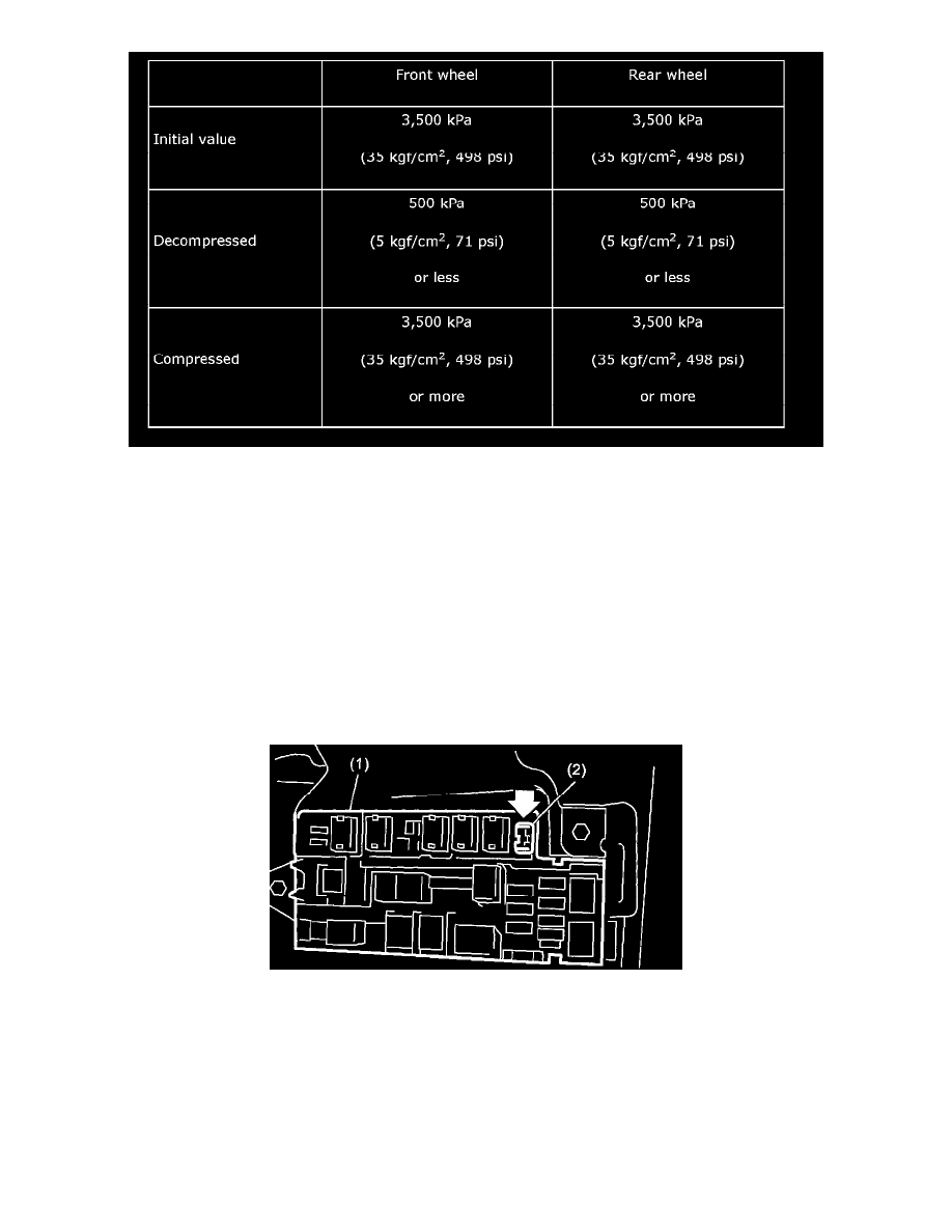
In the case of non-Saab 9-2X 2.OT Aero AT model, install a spare fuse with the FWD connector in the main fuse box to simulate FWD model.
(1) Main fuse box
(2) FWD connector
Note: The AWD circuit of MT and Saab 9-2X 2.OT Aero AT model can not be disabled.
Prepare for operating the ABS sequence control.
Set the front wheels or rear wheels on the brake tester and set the select lever's position at "N" range.