
9-7X L6-4.2L (2008)
‹› If communication is interrupted, test the serial data circuit between JX305 and the last module connected for a short to ground or a short to
voltage. If the circuit tests normal, replace the module that caused no communication.
Repair Instructions
Perform the Diagnostic Repair Verification (See: Testing and Inspection/Diagnostic Trouble Code Tests and Associated Procedures/Verification Tests
and Procedures) after completing the repair.
*
Control Module References (See: Testing and Inspection/Programming and Relearning/Control Module References) for module replacement,
setup, and programming
*
GMLAN Wiring Repairs (See: Testing and Inspection/Component Tests and General Diagnostics/Wiring Repairs/GMLAN Wiring Repairs)
Scan Tool Does Not Communicate with High Speed GMLAN Device
Scan Tool Does Not Communicate with High Speed GMLAN Device
Diagnostic Instructions
*
Perform the Diagnostic System Check - Vehicle (See: Testing and Inspection/Initial Inspection and Diagnostic Overview/Diagnostic System
Check - Vehicle) prior to using this diagnostic procedure.
*
Review Strategy Based Diagnosis (See: Testing and Inspection/Initial Inspection and Diagnostic Overview/Strategy Based Diagnosis) for an
overview of the diagnostic approach.
*
Diagnostic Procedure Instructions (See: Testing and Inspection/Initial Inspection and Diagnostic Overview/Diagnostic Procedure Instructions
)provides an overview of each diagnostic category.
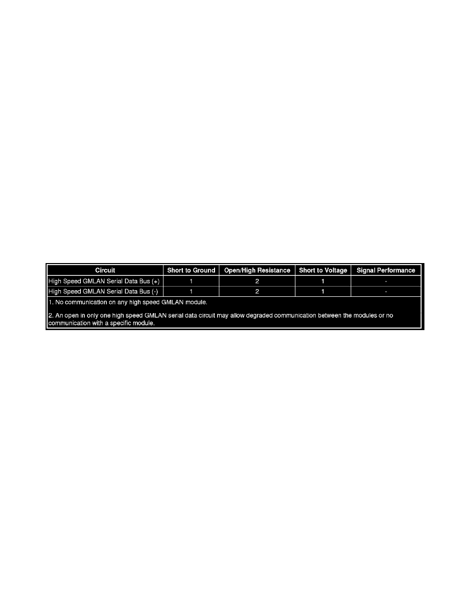
Diagnostic Fault Information
Circuit/System Description
Modules connected to the high speed GMLAN serial data circuits monitor for serial data communications during normal vehicle operation. Operating
information and commands are exchanged among the modules when the ignition switch is in any position other than OFF. The high speed GMLAN serial
data bus uses two 120 ohm terminating resistors that are in parallel with the high speed GMLAN (+) and (-) circuits. One of the resistors is connected
near the data link connector (DLC) end of the link and the other is internal to the engine control module/powertrain control module ECM/PCM end of
the link.
Diagnostic Aids
*
Use the Data Link References (See: Initial Inspection and Diagnostic Overview/Data Link References) to identify the high speed GMLAN serial
data modules.
*
This test is used for a total high speed GMLAN communication failure. If only 1 module is not communicating and sets no DTC, ensure that the
vehicle is equipped with the module, then use DTC U0100-U0299 (See: Testing and Inspection/Diagnostic Trouble Code Tests and Associated
Procedures/U Code Charts/U0100) for diagnostics.
*
The following conditions may cause a total loss of high speed GMLAN data communication:
^
A short between high speed GMLAN (+) and high speed GMLAN (-) circuits
^
Any of the high speed GMLAN serial data circuits shorted to ground or voltage
^
A module internal malfunction that causes a short to voltage or ground on the high speed GMLAN circuits
Reference Information
Schematic Reference
*
Data Communication Schematics (See: Diagrams/Electrical Diagrams)
*
Control Module References (See: Testing and Inspection/Programming and Relearning/Control Module References)
Connector End View Reference