
9000 L4-2290cc 2.3L DOHC Turbo EFI (1992)
Engine Control Module: Description and Operation
LH Control Module
Control Module
Description (LH 2.4, 2.4.1 and 2.4.2)
The control module in the LH 2.4 system has expanded memory capacity. Owing to this increased memory capacity, more checking and controlling
functions can be performed.
As a result of its memory expansion, the control module is fitted with a 35-pin connector instead of the 25-pin connector fitted previously.
For an overview of all control modules, see the Technical Data section.
Additional functions have been incorporated in the LH 2.4.1 control module. These are idle speed control and time-delay br AC engagement. In earlier
Systems, this time delay is obtained from a time- delay relay. In addition, the diagnostic function has been augmented.
The control module in the LH 2.4.2 system has a further augmentation of the diagnostic function. Additionally, the oxygen sensor engagement
condition when starting from cold has been changed and engagement is now controlled by time instead of by temperature as previously. As a result,
the theoretical limit for the start of idle speed control is lowered from 16°C to 0°C.
On cars equipped with the Traction Control System (TCS), idle speed control is effected by the ETS control module.
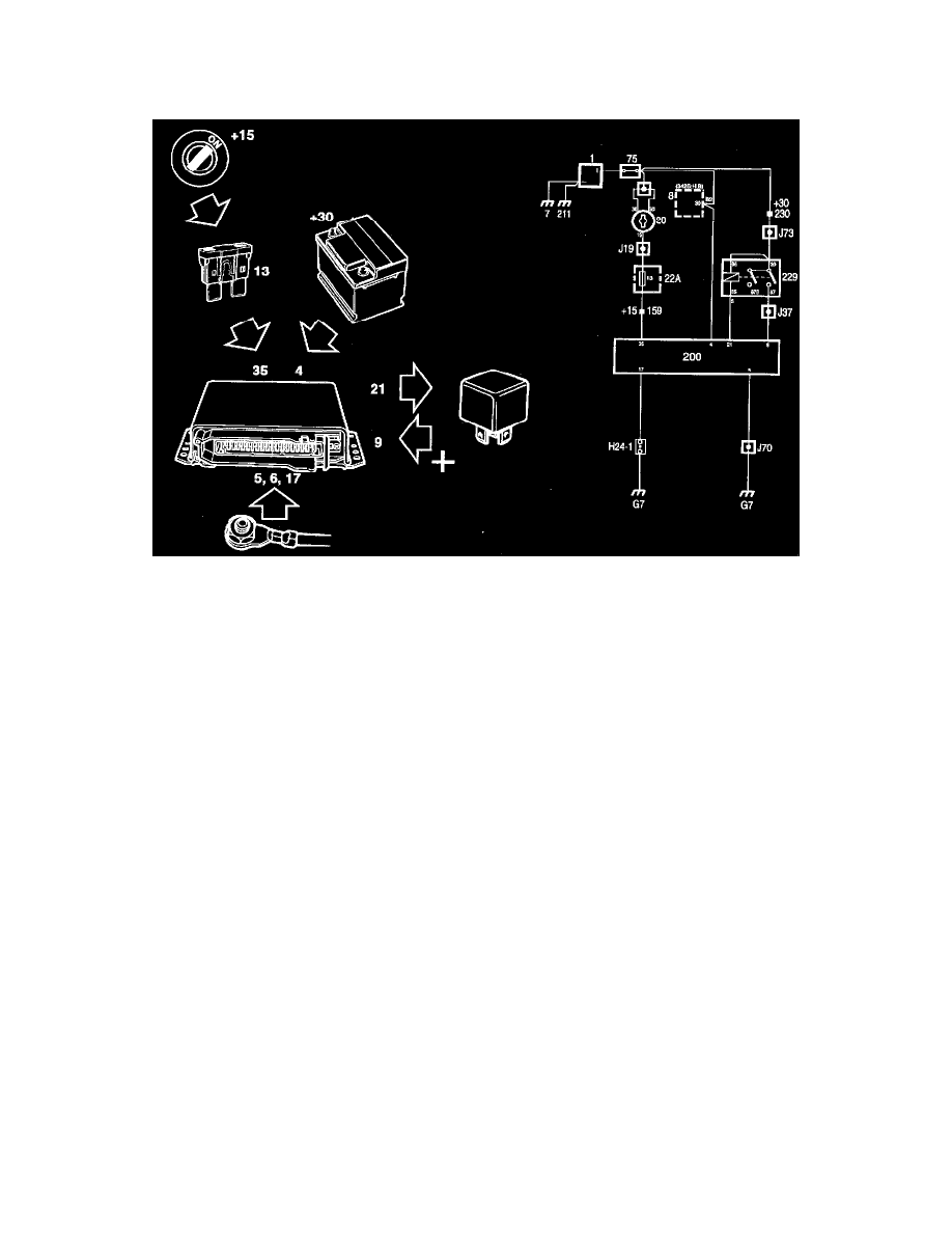
Power supply
The LH control module is supplied with power continuously via pin 4 (+30 supply). When the ignition switch is in the ON position, +15 current is also
supplied to pin 35 via fuse 13. Voltage to and from the main relay is supplied via pins 21 and 9.
The control module is connected to ground via pins 5, 6,17 and 18.