
900 SE Hatchback L4-1985cc 2.0L DOHC Turbo EFI (1997)
Shift Interlock Solenoid: Description and Operation
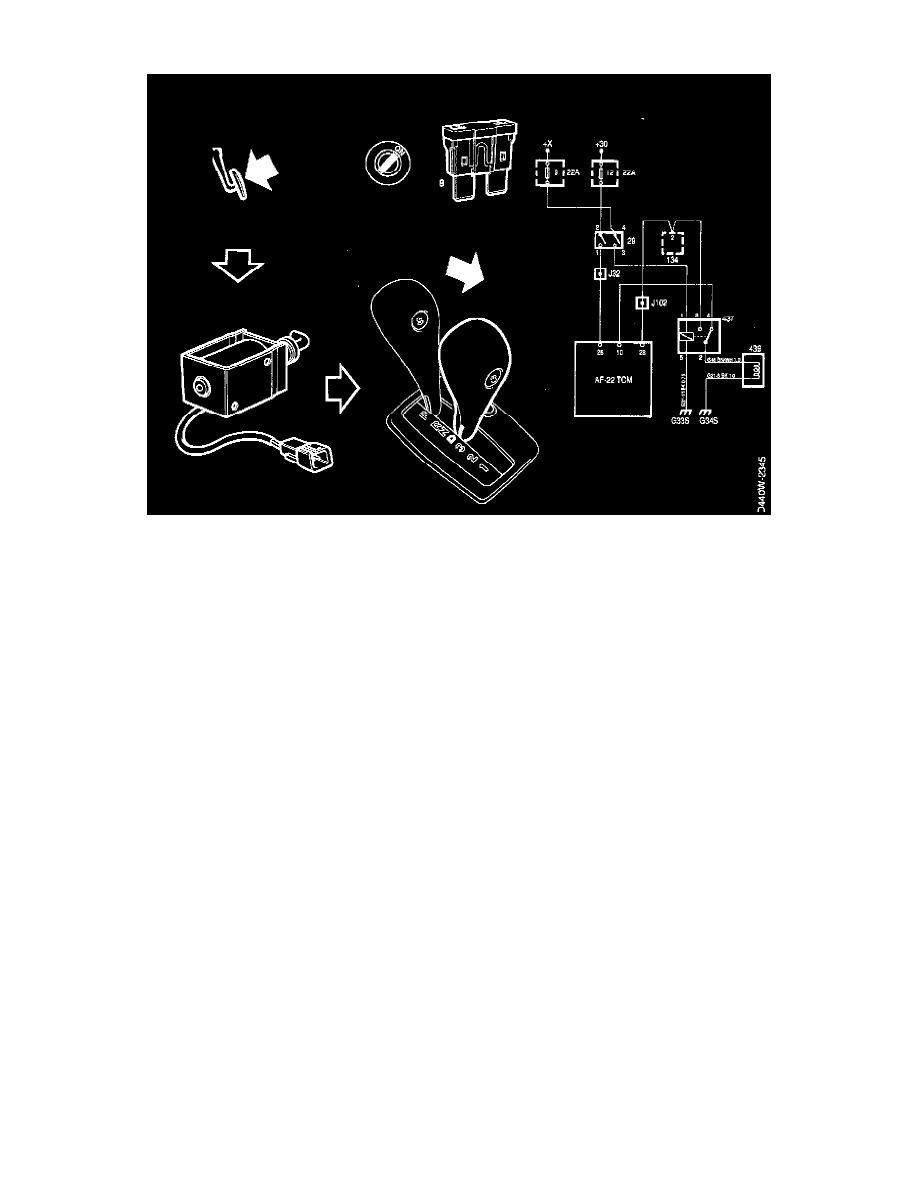
SHIFT-LOCK
For certain markets the transmission is delivered with a shift-lock function, which means that when the selector lever is in position P it is
impossible to move it unless the brake pedal is simultaneously depressed.
The shift-lock relay is connected, in parallel with two of the transmission range switch's contacts, to pins 10 and 28 on the TCM.
The shift-lock relay and its lifting magnet generate the SHIFT-LOOK function.
The shift-lock relay is fined in the distribution center under the main instrument. Because of the parallel connection mentioned above, a faulty
transmission range switch and a faulty shift-lock relay give the same fault-function on pins 10 and 28 and thus the same diagnostic trouble code
(P0705).
The lifting magnet is fitted in the selector lever's console and controls the operating ability of the selector lever. When starting with the selector
lever in position P, input signals B and 0 on the shift-lock are < 0.5 V. In all other gear selector positions one or both signals are battery positive
voltage.
A non-activated brake pedal gives battery positive voltage on input signal R. If the brake pedal is activated, 0.5 V is received. When all 3 input
signals to the relay are < 0.5 V, output 87 falls and the lifting magnet becomes passive. This makes operation of the selector lever possible.
The shift-lock function can be de-activated by removing fuse 9.