
Aura V6-3.5L (2007)
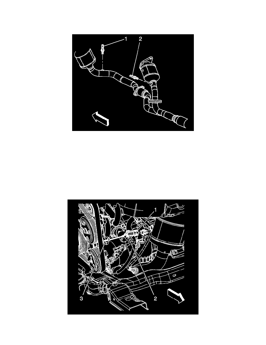
4. Remove the HO2S (1) using the J 39194-B.
Installation Procedure
Important: A special anti-seize compound is used on the HO2S 2 threads. The compound consists of graphite suspended in fluid and glass
beads. The graphite will burn away, but the glass beads will remain, making the sensor easier to remove. New or service sensors will
already have the compound applied to the threads. If a sensor is removed from an engine and is to be reinstalled, the threads must have
anti-seize compound applied before reinstallation.
1. Coat the threads of the HO2S with anti-seize compound GM P/N 12377953 or equivalent, if necessary.
Notice: Refer to Fastener Notice.
2. Install the HO2S (1).
Tighten the sensor to 42 N.m (31 lb ft) using the J 39194-B.
3. Connect the HO2S electrical connector to the engine wiring harness electrical connector (2).
4. Install the CPA retainer (3).
5. Lower the vehicle.