
ION L4-2.0L SC (2007)
6. Using the J 39194 carefully remove the HO2S.
7. Lower the HO2S electrical harness away from the underbody.
Installation Procedure
Important: A special anti-seize compound is used on the HO2S threads. The compound consists of a liquid graphite and glass beads. The
graphite will burn away but the glass beads will remain, making the sensor easier to remove. New or service sensors already have the
compound applied to the threads. If the sensor is removed and is to be reinstalled, the threads must be coated with an anti-seize compound
before reinstallation.
1. If reinstalling the old HO2S, coat the threads with anti-seize compound, Saturn P/N 24185279, or equivalent.
2. Carefully install the HO2S to the pipe.
Notice: Refer to Component Fastener Tightening Notice.
3. Using the J 39194 , or equivalent, tighten the HO2S.
Tighten the HO2S to 41 N.m (30 lb ft).
4. Install the HO2S electrical harness into position as noted before removal.
Important: Use care when securing the HO2S electrical harness into the channel on the exhaust heat shield, to not pinch the wires.
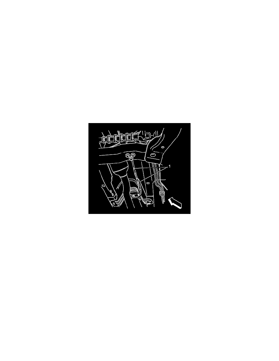
5. Carefully bend the edge of the channel (1) on the LH side of the exhaust heat shield inboard, just enough to secure the HO2S electrical harness in
the channel.