
ION L4-2.2L VIN F (2004)
2. Enable the circuit and/or system being tested. Use the following methods:
-
Turn ON the ignition, with the engine OFF.
-
Turn ON the engine.
-
Turn ON the circuit and/or system with a scan tool in Output Controls.
-
Turn ON the switch for the circuit and/or system being tested.
3. Select the V (AC) or V (DC) position on the DMM.
4. Connect the positive lead of the DMM to the point of the circuit to be tested.
5. Connect the negative lead of the DMM to a good ground.
6. The DMM displays the voltage measured at that point.
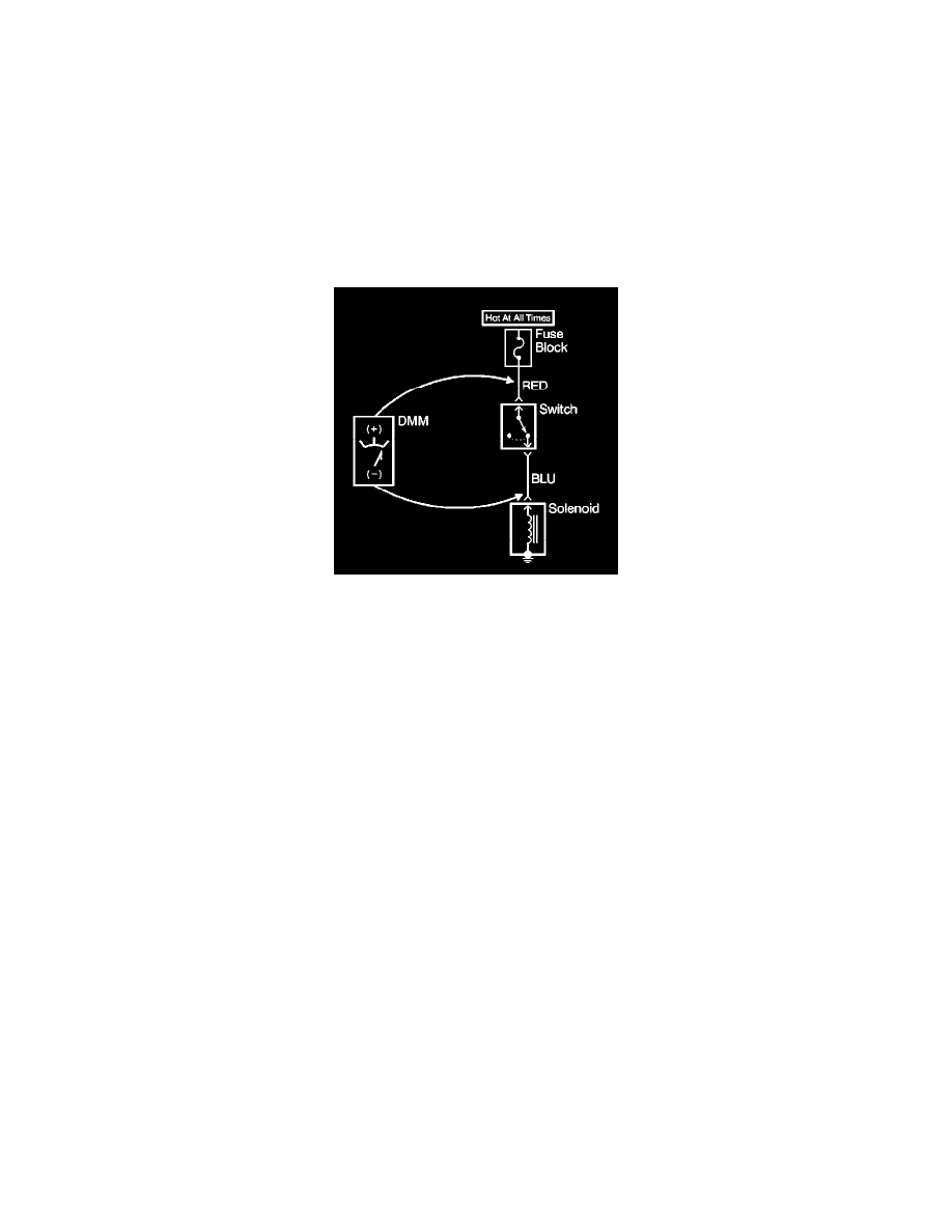
Measuring Voltage Drop
MEASURING VOLTAGE DROP
NOTE: Refer to Test Probe Notice in Service Precautions.
The following procedure determines the difference in voltage potential between 2 points.
1. Set the rotary dial of the DMM to the V (DC) position.
2. Connect the positive lead of the DMM to 1 point of the circuit to be tested.
3. Connect the negative lead of the DMM to the other point of the circuit.
4. Operate the circuit.
5. The DMM displays the difference in voltage between the 2 points.
Probing Electrical Connectors
PROBING ELECTRICAL CONNECTORS
IMPORTANT: Always be sure to reinstall the connector position assurance (CPA) and terminal position assurance (TPA) when reconnecting
connectors or replacing terminals.
Frontprobe
Disconnect the connector and probe the terminals from the mating side (front) of the connector.
NOTE: Do not insert test equipment probes into any connector or fuse block terminal. The diameter of the test probes will deform most terminals. A
deformed terminal can cause a poor connection, which can result in system failures. Always use the J 43907 Connector Test Adapter Kit in order to
frontprobe terminals. Do not use paper clips or other substitutes as they can damage terminals and cause incorrect measurements.
Backprobe
IMPORTANT
-
Backprobe connector terminals only when specifically required in diagnostic procedures.
-
Do not backprobe a sealed (Weather Pack(r)) connector, less than a 280 series Metri-Pack connector, a Micro-Pack connector, or a flat wire (dock
and lock) connector.
-
Backprobing can be a source of damage to connector terminals. Use care in order to avoid deforming the terminal, either by forcing the test probe
too far into the cavity or by using too large of a test probe.
-
After backprobing any connector, inspect for terminal damage. If terminal damage is suspected, test for proper terminal contact.
Do not disconnect the connector and probe the terminals from the harness side (back) of the connector.
Scan Tool Snapshot Procedure
SCAN TOOL SNAPSHOT PROCEDURE