
L200 L4-2.2L VIN F (2002)
Power Mirror Switch: Description and Operation
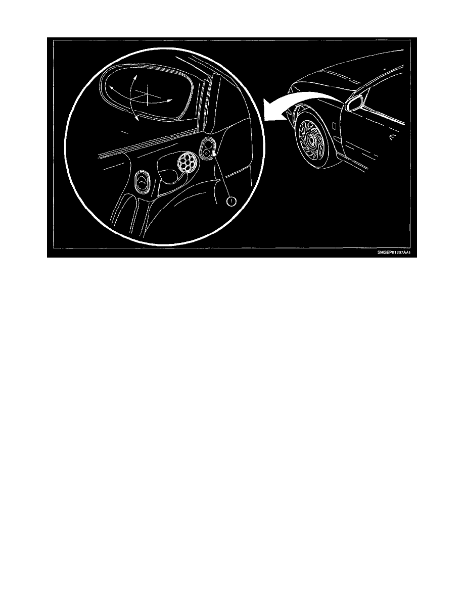
Power Mirror Switch
The power mirror switch controls right and left mirror position. The mirror select switch (rocker switch) allows control of the right or left mirror. The
mirror adjustment switch (pad switch) allows control of the mirror position: UP, DOWN, RIGHT, or LEFT.
With the mirror select switch in LEFT mirror position, the circuit operation is as follows:
If the mirror adjustment switch is pressed in UP position, battery voltage from circuit 743 is applied to circuit 881 to the up/down mirror motor in left
mirror. The mirror switch supplies a ground path for circuit 82 through the closed contacts to circuit 550, and the mirror moves up. When the mirror
adjustment switch is pressed in the DOWN position, battery voltage from circuit 743 is applied through to circuit 82 to the up/down mirror motor in left
mirror. The mirror switch supplies a ground path for circuit 881 through the closed contacts to circuit 550, and the mirror moves down.
When the mirror adjustment switch is moved to RIGHT position, battery voltage from circuit 743 is applied through to circuit 889 to the right/left mirror
motor in left mirror. The mirror switch supplies a ground path for circuit 82 through the closed contacts to circuit 550, and mirror moves right. When the
mirror adjustment switch is moved to LEFT position, battery voltage from circuit 743 is applied through to circuit 82 to the right/left mirror motor in the
left mirror. The mirror switch supplies a ground path for circuit 889 through the closed contacts to circuit 550, and the mirror moves left. The controls of
the mirror position switch are the same for the right and left position of the mirror select switch.
With the mirror select switch in RIGHT mirror position, the circuit operation is as follows:
If the mirror adjustment switch is pressed in UP position, battery voltage form circuit 743 is applied to circuit 81 to the up/down mirror motor in left
mirror. The mirror switch supplies a ground path for circuit 82 through the closed contacts to circuit 550, and mirror moves up. When the mirror
adjustment switch is pressed in the DOWN position, battery voltage from circuit 743 is applied through to circuit 82 to the up/down mirror motor in right
mirror. The mirror switch supplies a ground path for circuit 81 through the closed contacts to circuit 550, and the mirror moves down.
When the mirror adjustment switch is moved to RIGHT position, battery voltage from circuit 743 is applied through to circuit 89 to the right/left mirror
motor in right mirror. The mirror switch supplies a ground path for circuit 82 through the closed contacts to circuit 550, and the mirror moves right.
When the mirror adjustment switch is moved to LEFT position, battery voltage from circuit 743 is applied through to circuit 82 to the right/left mirror
motor in right mirror. The mirror switch supplies a ground path for circuit 89 through closed contacts to circuit 550, and the mirror moves left. The
controls of the mirror position switch are the same for the right and left position of the mirror select switch.