
L300 V6-3.0L VIN R (2001)
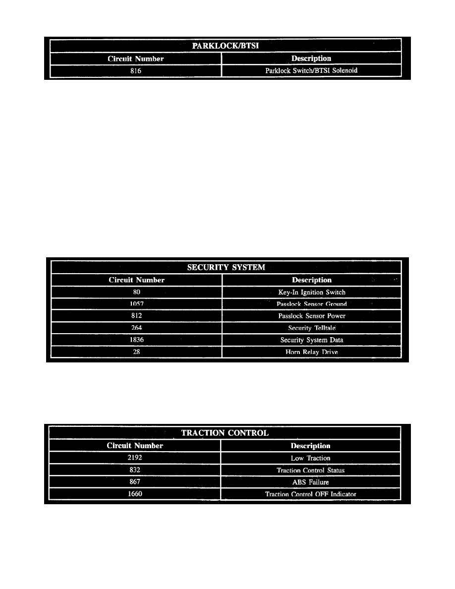
Parklock/BTSI Circuit Chart
Circuit Chart
Circuit assignments for the Body Control Module (BCM) relating to parklock/BTSI:
Power Mode
The BCM monitors ignition 1 voltage circuit 339, ignition 2 voltage circuit 743 and the Engine Run Flag (ERF). The ERF is a serial data message from
the engine controller. The BCM determines the state of the ignition switch for all modules on the serial data link.
Security System
The passlock sensor is powered by circuit 812. The passlock sensor is grounded by circuit 1057. Passlock sensor data is supplied to the BCM by circuit
1836.
The passlock sensor data supplied to the BCM is in the form of V-codes or voltage codes. When the proper ignition key is turned in the ignition switch,
the correct V-code is supplied to the BCM. The BCM responds by sending a serial data password to the engine controller allowing the engine to run.
The security resistor is bypassed under a tamper condition (possible external magnet applied to sensor). In this mode, a specific V-code is supplied to the
BCM. The vehicle will not start in this mode.
Security System Circuit Chart
Security System Circuit Check
Circuit assignments for the Body Control Module (BCM) relating to security system:
Traction Control Circuit Chart
Circuit Chart
Circuit assignments for the Body Control Module (BCM) relating to traction control system:
Traction Control System Off Indicator
When the traction control system is in the On state, the traction control Light Emitting Diode (LED) request from the Electronic Brake Traction Control