
L300 V6-3.0L VIN R (2001)
This process of learning by a module allows the module to know if it has lost communication with a specific module on the class II data circuit.
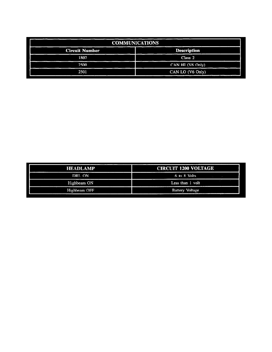
Communications Circuit Chart
Circuit Chart
Circuit assignments for the Body Control Module (BCM) relating to communications:
Coolant Level
When engine coolant is at the proper level, the low coolant switch is closed. When in this condition, battery voltage is applied to the low coolant circuit
1478 input of the BCM.
When coolant is below the proper level, the low coolant switch opens. Because no voltage is applied to circuit 1478 the BCM responds by sending a
serial data message to the instrument panel cluster to turn On the low coolant telltale.
The BCM has an internal timer, which will not turn On the low coolant telltale unless the coolant level is low for greater than 30 seconds. The timer
avoids coolant sloshing falsely turning On the low coolant telltale.
Daytime Running Lamps
Daytime Running Lamps (DRL) are controlled by the BCM based on input from the high beam headlamp circuit 1200, the low beam headlamp circuit
1201, the parking brake circuit 1134 and ignition switch state.
When DRL operation is desired, the BCM switches circuit 592 to ground. This action energizes the DRL relay. When energized, the DRL relay operates
the left high beam headlamp and right high beam headlamp as a series circuit (one-half of battery voltage across each high beam headlamp).
When DRL operation is not desired, the BCM does not provide ground for the DRL relay. When not energized (as when high beam headlamps are
desired) the DRL relay operates the right and left high beam headlamps as a parallel circuit (full battery voltage across each high beam headlamp).
For DRL operation, the parking brake must be fully released, the ignition switch must be in the RUN position and headlamp switch must be in the Off
position. Under normal operating conditions, the feedback voltage to the BCM measured at circuit 1200 is:
Decklid/Liftgate Release
The trunk/liftgate release is controlled by the Body Control Module (BCM) circuit 382 providing battery voltage to the release solenoid. The BCM
limits the amount of time the solenoid can be activated to 9 seconds to prevent damage to the solenoid. Reactivation may not be allowed for as much as
30 seconds.
Release of the decklid/liftgate can be initiated by either the transmitter or the decklid/liftgate release switch. Activating the decklid/liftgate release switch
provides battery voltage to circuit 56. Because remote keyless entry is an internal function of the BCM, no additional external wiring is necessary for
transmitter input to the BCM. Decklid/liftgate release is not allowed by the BCM when vehicle speed is detected. The BCM receives vehicle speed serial
data from the engine controller. Trunk release in sedan vehicles has a valet switch to limit trunk access.
The BCM also monitors the state of the decklid/liftgate. When circuit 744 is grounded by the ajar switch, the BCM will alert the driver the
decklid/liftgate is ajar by turning On the ajar telltale.
Delayed Locking
The delayed locking feature will activate when a valid lock command is received from a transmitter while any door or trunk (hatch) remains open. The
BCM will delay locking the vehicle until all doors and deck lid (hatch) are closed. The lock command will execute with in 500 mS, after all doors and/or