
LS2 V6-3.0L VIN R (2000)
Circuit Chart
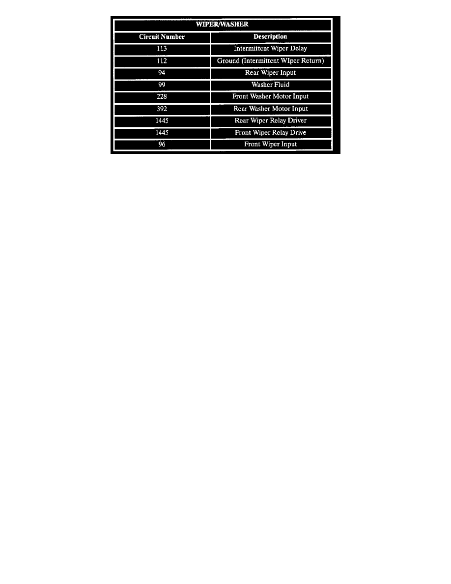
CIRCUIT CHART
Circuit assignments for the Body Control Module (BCM) relating to wiper/washer:
INTERMITTENT WIPER DELAY
The intermittent wiper delay switch is a voltage divider connected across BCM inputs circuit 113 and circuit 96. The wiper relay is energized by the
BCM switching circuit 1445-to-ground depending on delay switch position.
The intermittent wiper delay switch has three switch positions.
^
Delay 3(2000 ohms resistance, one swipe every 12 seconds)
^
Delay 2(1000 ohms resistance, one swipe every 7 seconds)
^
Delay 1(500 ohms resistance, one swipe every 2 seconds)
FRONT WASHER MOTOR
The body control module (BCM) monitors the front washer motor circuit 228. When a front windshield wash is requested for more than two minutes
circuit 228 at battery voltage, the BCM will turn OFF the front wiper motor if the front wiper is NOT requested by the wiper switch.
Power for the front washer motor (and rear washer motor when equipped) is supplied through the front wiper fuse and washer switch. Grounding for
the front washer motor is through the (circuit 550) or through the OFF position of the rear washer motor switch (when equipped).
REAR WASHER MOTOR
The BCM monitors the rear washer motor circuit 392. When a rear windshield wash is requested for more than two minutes circuit 392 at battery
voltage, the BCM will turn Off the rear wiper motor if the rear wiper is NOT requested by the wiper switch.
Power for the rear washer motor is supplied through the front wiper fuse and rear washer switch. Grounding for the rear washer motor is through the
OFF position of the front washer motor switch.
FRONT WIPER CONTROL
When intermittent or mist operation of the windshield wiper is selected, battery voltage from the wiper switch is applied to the front wiper input of the
BCM. The BCM responds by switching circuit 1445-to-ground. This action energizes the front wiper relay, providing low speed operation of the
wiper motor during single swipes.
Control of the wiper during continuous LO or HI speed switch settings is direct wired from the wiper switch to the wiper motor and is not under the
control of the BCM.
REAR WIPER CONTROL
When operation of the rear wiper is selected, battery voltage from the rear wiper switch is applied to the rear wiper input of the BCM circuit 94. The
BCM responds by switching circuit 1445-to-ground. This action energizes the rear wiper relay, providing power to the rear wiper motor.