
SW1 L4-1.9L SOHC VIN 8 (1996)
Diagram
SERIAL COMMUNICATIONS
Scan tool operation is accomplished with bi-directional communication between the tool and the PCM. OBD II technology requires a much more
sophisticated PCM than did OBD I technology. The PCM diagnostic management system not only monitors systems and components that impact
emissions, but also runs active tests on these systems and components. To accommodate this expansion a Class 2 serial data bus is used which
meets SAE J1850 specifications for serial data.
"Serial Data" refers to digital information which is transferred over a single line, one bit at a time. A "Data Bus" is an electronic pathway through
which digital data travels.
96 Saturn vehicles use a 5 volt data bus called UART, which is an acronym for universal asynchronous receive and transmit. When neither the
Scan tool nor the PCM are communicating, the voltage level of the bus at rest is 5 volts. The Scan tool and PCM communicate by toggling or
switching the data bus from 5 volts to ground.
Class 2 data, which is used on OBD II vehicles, communicates at a much faster rate. The rest voltage on a Class II bus is 0 volts and is switched
high (7 volts) when communications are taking place.
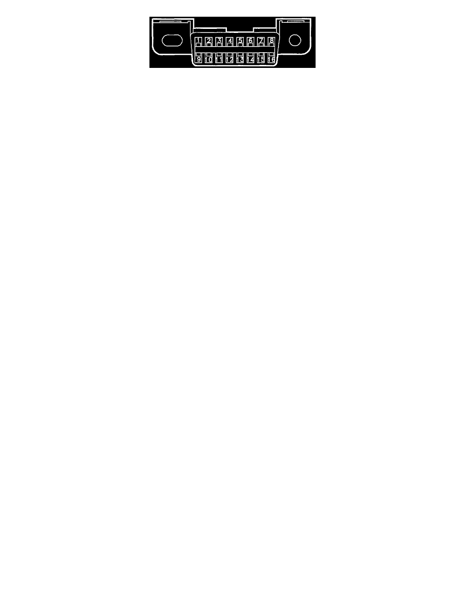
OBD II also standardizes the data link connectors (DLC). The DLC used is a 16 pin as compared to the 12 pin connector used in previous years.
All manufacturers must conform to the 16 terminal standard.
CRANKSHAFT LEARN
The PCM uses crankshaft velocity calculations to determine misfire and run misfire self-diagnostics. The PCM must know precisely the variability
in crankshaft notches for this function. The PCM has a "notch learn" process that learns the variability between notches which must be reset if the
crankshaft in the engine is replaced. With use of the SSS, the crankshaft learn procedure can be set to relearn.
NOTE: Do not transfer PCM's from one vehicle to another. The learned crankshaft notches will be different from one vehicle to another.
NOTE: Anytime a replacement PCM is installed the PCM must relearn the crankshaft notches.
CRANKSHAFT RELEARN PROCEDURE
When a replacement PCM is installed, or the crankshaft or engine has been replaced, follow these procedures to relearn the crankshaft notches:
1. Allow the engine to idle until the SERVICE telltale flashes.
2. Hold rpm level to 3000 rpm until lamp goes Off (approx 10-20 seconds).
NOTE: This procedure will not be initiated if any misfire is detected. If misfire codes are present refer to Misfire Diagnosis section prior to
attempting to relearn crankshaft notches. See: Description and Operation/General System Description/Powertrain Control
System/Specific/Random Cylinder Misfire Detection
NOTE: If the Scan tool or service stall system are used to "reset" the crank shaft learn, the ignition will have to be cycled off for 10 seconds to
correctly initiate the process.