
SW1 L4-1.9L SOHC VIN 8 (1996)
8. Insert the terminal into the connector. Check to make sure the terminal lock tab is engaged by gently tugging on the wire.
9. Replace any terminal position assurance (TPA) devices.
IMPORTANT: The salmon splice can be used on the 0.35 (22 gage) wire if the following additional steps are taken:
10. Remove 19 mm (3/4 in.) of insulation.
11. Bend the stripped portion in half to double the thickness.
12. Twist the stripped, doubled wire and insert into the splice sleeve.
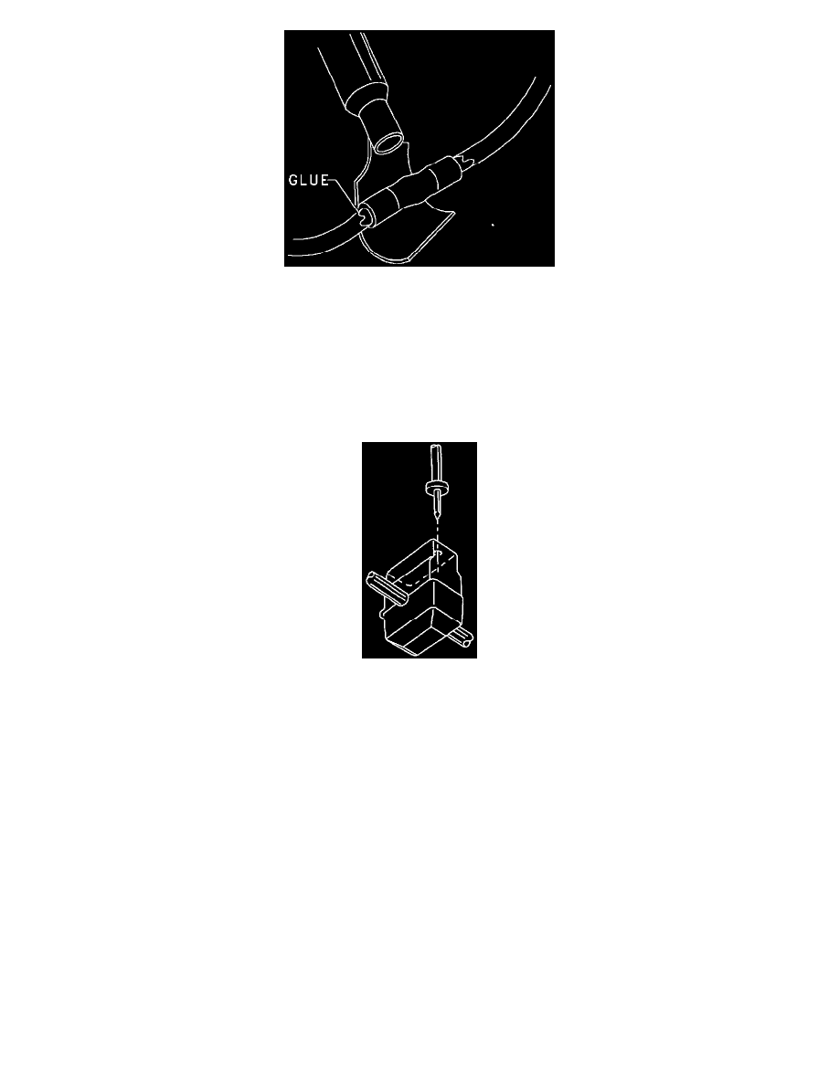
Diagnostic Service Probe
Diagnostic Service Probe
IMPORTANT: Diagnostic service probes are for use on 0.35, 50 and 0.80 mm (22, 20 and 18 gage) wires only.
IMPORTANT: The diagnostic service probes must be left on the wire after use. The probe contains a sealant that will protect the wire from corrosion.
Do not remove the diagnostic service probe after use.
The use of the diagnostic service probe offers many advantages in system diagnostics over the old jumper wire and terminal back-probe methods. The
most important advantage of the diagnostic service probe method of diagnostics is the ability to observe the operation of a circuit without disturbing the
components or connections. This is an important advantage since many circuit failures are vibration or connection related. The diagnostic service probe
is designed to firmly hold multimeter test probes to allow more accurate readings while the circuit is operating. Circuits with bad connectors, grounds or
components are easier to diagnose while they are operating.
Attach the diagnostic service probe to the wire leading to the connector and insert your multimeter into the diagnostic service probe. Put the meter on the
appropriate scale and observe the readings. If the readings do not compare with the expected readings, gently wiggle the wire back and forth in the
connector. If the reading on the meter changes while you are wiggling the wire, the terminal or connector are faulty. Disconnect the connector and
examine the terminals and connector cavities for damage. Check the terminals to see if a known good terminal makes a firm connection. Do this by
inserting a known good male terminal into the female terminal you are testing. The male terminal should be held firmly in place by the female terminal
and should not be loose enough to fall out if the female terminal is held downward. Likewise, test a male terminal by inserting it into a known good
female terminal. The two terminals should fit snugly together and should not separate if the male terminal is held vertically downward.
If the connections are good (both wire connections and the connection to the component), check the ground connection. Attach a diagnostic service
probe to the ground side of the circuit or component. Place a multimeter probe in the diagnostic service probe and the other probe to a known good
ground.