
SW1 L4-1.9L SOHC VIN 8 (1996)
Assembly View
4. Disconnect electrical connectors from selector switch.
5. Disconnect shifter cable from control lever.
6. Place control lever in the full clockwise position.
NOTE: If manual shift shaft is rotated excessively, internal damage to the park/neutral position switch may occur.
7. Prevent the manual shift shaft from rotating by holding the control lever while removing retaining nut from manual shift shaft. Remove control
lever.
8. Remove two switch-to-transaxle case bolts and remove switch.
INSTALLATION
1. Install switch to transaxle and install switch to case bolts. Do not tighten bolts at this time.
2. Install control lever-to-manual shift shaft.
NOTE: If manual shift shaft is rotated excessively, internal damage to the park/neutral position switch may occur.
3. Prevent the manual shift shaft from rotating by holding control lever while installing retaining nut.
- Torque: 12 N.m (106 in-lbs)
4. Refer to adjustment procedure.
ADJUST AND FINALIZE ASSEMBLY
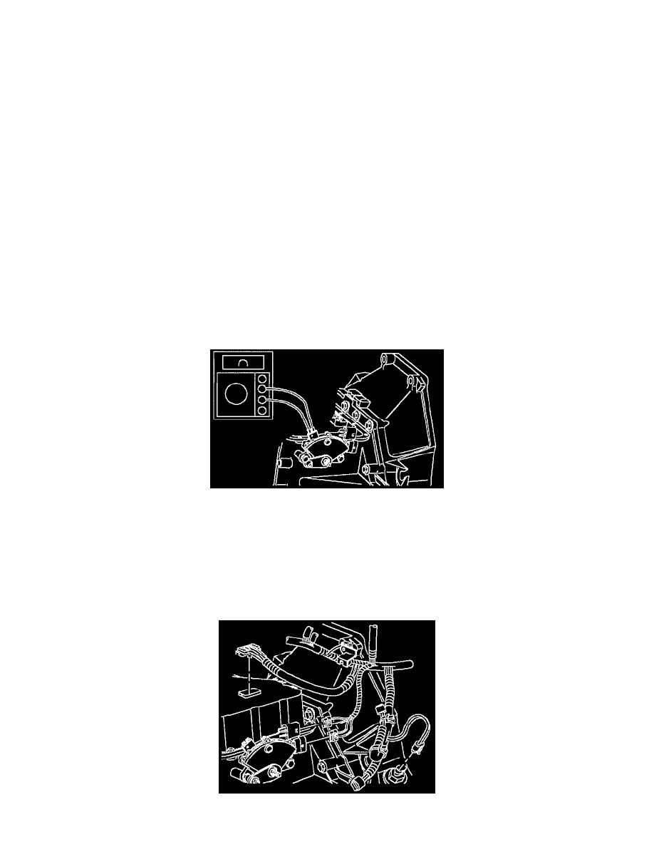
Ohmmeter Hook-up
1. Place transaxle in D (Drive). Use ohmmeter or continuity tester to check for continuity across terminals on switch. If no continuity is present,
loosen mounting bolts and rotate switch to achieve continuity.
2. Tighten switch to case bolts. After switch to case bolts have been tightened, check continuity.
- Torque: 14 N.m (124 in-lbs)
NOTE: DVM with audible continuity test is preferred. Do not stick probe in terminal hole; use male terminals on switch or faulty readings could
exist.
Connector Hook-ups