
SW1 L4-1.9L SOHC VIN 8 (1996)
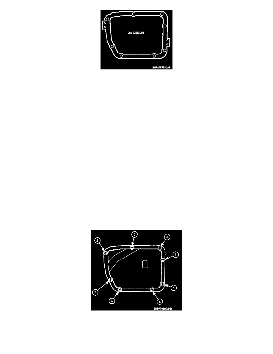
The two illustrations shown illustrate the differences between the first and second design valvebody cover gaskets. The transaxle case and valvebody
cover have also been changed to reflect the reduction in fasteners.
The second design parts are not compatible with the first design parts. First design valvebody covers, valvebody gaskets and valvebody bolts will
continue to be available for servicing vehicles listed under "Models Affected" in this bulletin. If a transaxle case requires replacement, only a second
design transaxle case is available from Saturn service parts. When replacing a first design transaxle case, a second design valvebody cover, valvebody
cover gasket and valvebody bolts must be used.
IMPORTANT:
1991 vehicles, and 1992 vehicles not listed under "Models Affected" in this bulletin, continue to be serviced with parts specific for these vehicles.
Refer to Saturn Parts Catalog for correct part numbers.
Due to the differences between the first design and second design parts, when installing a second design valvebody cover, perform the following
procedure.
IMPORTANT:
The following procedure is included in the "1997 Automatic Transaxle Service Manual."
1.
Clean transaxle case and valvebody cover sealing surfaces with Saturn Brake and Choke Cleaner (P/N 21007432) or equivalent with a clean shop
towel
2.
Position valvebody cover gasket on to transaxle case.
3.
Align valvebody cover to valvebody cover gasket and transaxle case and install valvebody cover to transaxle case.
NOTICE:
When installing the valvebody cover, it is important to clean and lubricate fasteners with Saturn Transaxle Fluid (or equivalent), or sufficient clamp
load of the gasket will not be achieved.
4.
Clean and lubricate transaxle cover bolts with Saturn Transaxle Fluid (or equivalent). Wipe off excess fluid and install valvebody cover bolts.
5.
Torque transaxle cover bolts according to the torque sequence shown in the illustration.
Torque: 12 N.m (106 in-lbs)
6.
Re-torque valvebody cover bolts, using the torque sequence shown in illustration, to account for gasket relaxation.