
VUE AWD V6-3.5L VIN 4 (2004)
15.
Reinstall connector to PCM and verify condition(s) are corrected.
Terminal Replacement
Installing New Electrical Lead Kit
Important:
Use only Saturn/GM splice sleeves. Other splice sleeves may not protect the splice from moisture or provide a good electrical connection.
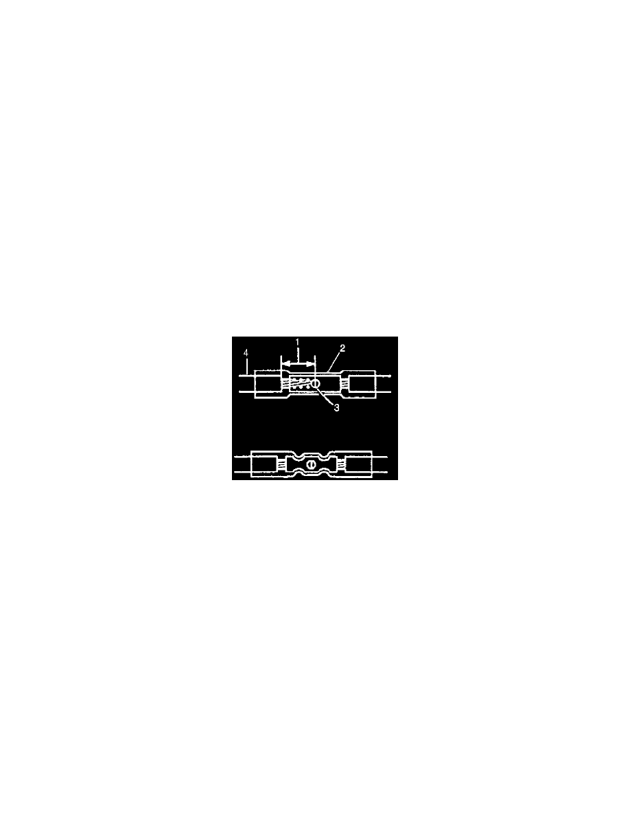
1.
Open the harness.
^
If the harness is taped, remove the tape.
^
To avoid wiring insulation damage, use a sewing ripper (or equivalent) to cut open the harness.
^
If the harness has a black plastic conduit, pull out the desired wire.
2.
Cut the wire.
^
Cut as little wire off the harness as possible.
^
Ensure that each splice is at least 40 mm (1.5 in) away from other splices, harness branches and connectors. This helps prevent moisture from
bridging adjacent splices and causing damage.
^
Trim new cut lead wire, P/N 22692904, to same length as damaged wire removed from connector.
3.
Strip the insulation approximately 7.5 mm (5/16 in) from each wire to be spliced (1).
4.
Place the provided splice sleeve in the 12085115 crimp tool nest (or equivalent) so that the crimp falls at point 1 on the splice.
5.
Close handles of 12085115 crimp tool, or equivalent, slightly to hold the splice sleeve firmly in the proper crimp tool nest.
6.
Insert the wires into the splice sleeve until the wire hits the barrel stop. The splice sleeve has a stop in the middle of the barrel to prevent the wire
from passing through the splice (3).
7.
Close the handles of the 12085115 crimp tool, or equivalent, until the crimper handles open when released. The crimper handles will not open
until the proper amount of pressure is applied to the splice sleeve. (Repeat for other half of splice sleeve.)
8.
Shrink the insulation around the splice.
Caution:
Follow manufacturer's instructions to avoid personal injury. Do not use match or open flame to apply heat.
9.
Seal splice sleeve by applying heat using Ultra Torch J 38125-5A, or equivalent, heating to 175°C (347°F) until glue flows around edges of splice
sleeve.
10.
Reinstall new cut lead(s) into correct connector cavity. Verify that when the new terminal is installed, there is an audible click. Perform a tug test
on the newly installed wire.
11.
Proceed to Step 11 in the "Terminal Removal/Replacement" procedure in this bulletin.