
Leon Mk1
| Differential: dismounting and assembling |
| t | The differential must be adjusted whenever the tapered roller bearings are replaced. Consult the Adjustments Chart → Chapter. |
| t | The tapered roller bearings must always be replaced together. |
| t | The tapered roller bearings and their corresponding outer tracks come in pairs. Do not mix them up or exchange them with other bearings. |
| Assembly chart |

| 1 - | Gearbox casing |
| 2 - | Bolt |
| 3 - | Differential box |
| q | In the event of replacement, consult the Adjustments Chart → Chapter. |
| 4 - | Crown for the riveted differential |
| q | Factory riveted |
| q | Assembly with bolts → Chapter |
| q | In the event of replacement, the crown of the differential and the secondary shaft must be replaced together. |
| q | Dismounting and assembly → Chapter, Crown of the differential: dismounting and assembling |
| 5 - | Plate washer |
| 6 - | Nut, 70 Nm |
| 7 - | Adjustment washer |
| q | Determine the thickness → |
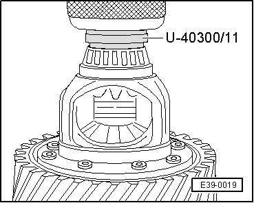
| 8 - | Outer track, tapered roller bearing |
| q | Dismount → Fig. |
| q | Assemble → Fig. |
| 9 - | Tapered roller bearing |
| q | Dismount → Fig. |
| q | Assemble → Fig. |
| 10 - | Differential unit |
| q | In the event of replacement, the crown of the differential and the secondary shaft must be replaced together. Consult the Adjustments Chart → Chapter. |
| q | Factory riveted crown. |
| q | Drilling of the rivets and assembly with bolts → Chapter |
| 11 - | Pinion for working the speedometer |
| q | Dismount it by levering with a flat screwdriver. |
| q | Assembly: fit it in up to the top in the differential box before assembling the tapered roller bearing → Item. |
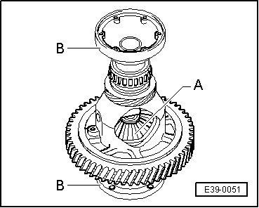
| 12 - | Tapered roller bearing |
| q | Dismount → Fig. |
| q | Assemble → Fig. |
| 13 - | Outer track, tapered roller bearing |
| q | Dismount → Fig. |
| q | Assemble → Fig. |
| 14 - | Clutch casing |
| 15 - | Bush |
| q | Retainer for the coupling flange |
| q | Dismount and assemble → Chapter |
| 16 - | Retainer for the coupling flange |
| q | Replace → Chapter |
| 17 - | Bolt, 25 Nm |
| q | Screw in with the threaded part for attaching the coupling flanges → Item. |
| 18 - | Coupling flanges |
| q | Dismount and assemble → Chapter |
| 19 - | Spring for coupling flange |
| q | Assemble it behind the coupling flange. |
| 20 - | Front washer |
| q | Position for assembly: Collar facing towards the spring, core facing towards the tapered ring. |
| 21 - | Tapered ring |
| q | With trimmings for fitting the front washer |
| q | Position for assembly: tapered side facing towards the differential box. |
| 22 - | Safety ring |
| q | Keeps the tapered ring, the washer and the spring for the coupling flange in position when the latter is dismounted. |
| 23 - | Set of friction washers |
| q | Coat them with gearbox oil before assembling them. |
| 24 - | Differential side gear |
| q | Assemble → Fig. |
| 25 - | Threaded part for attaching the coupling flanges |
| q | Assemble → Fig. |
| 26 - | Axle for satellites |
| q | Dismount it by striking with a punch. |
| 27 - | Elastic linchpin |
| q | Dismount it by striking with a suitable punch. |
| q | Assemble ⇒ Fit it up to the stop. |
| 28 - | Satellite |
| q | Assemble → Fig. |
| 29 - | Differential side gear |
| q | Assemble → Fig. |
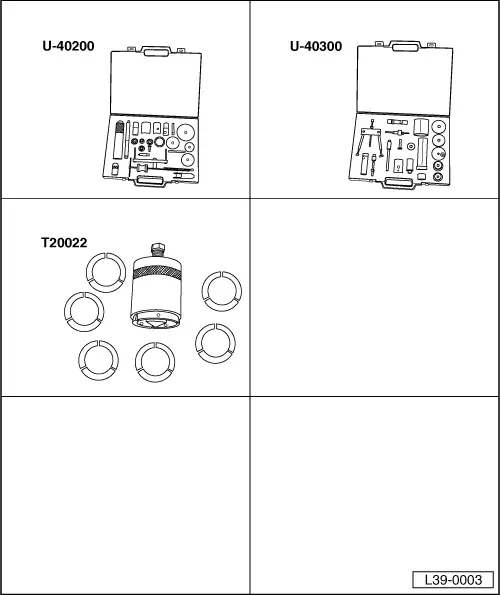
| Special tools and workshop equipment required |
| t | Case of tools for repairing gearboxes -U-40200- |
| t | Case of tools for repairing gearboxes -U-40300- |
| t | Pincer extractor tool with grippers -T20022- |
 Note!
Note!
|
|
|
|
Note!
|
|
|
|