
Leon Mk1
| Input shaft: dismantling and assembling |
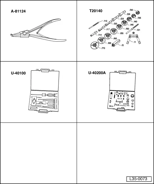
| Special tools and workshop equipment required |
| t | Pliers -A-81124- |
| t | Kit -T20140- |
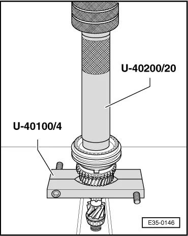
| t | Kit -U-40100- |
| t | Kit -U-40200 A- |
 Note!
Note!| t | Whenever new gears are fitted consult the technical data → Chapter. |
| t | The input shaft must be adjusted whenever elements have been replaced which could affect the position of the roller bearings. Refer to Adjustment chart → Chapter. |
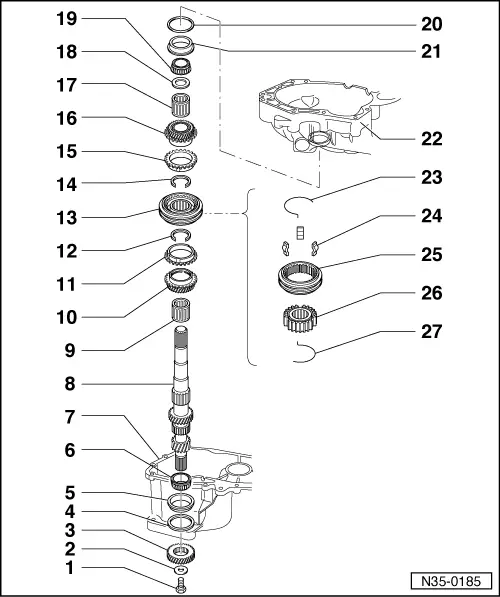
| 1 - | M8 Torx screw, 40 Nm |
| 2 - | Plate spring |
| 3 - | 5th gear |
| q | Removing and installing → Chapter, assembly sequence |
| 4 - | Washer |
| q | Always 1 mm thick |
| q | Fitted to gearboxes manufactured from 07.97, except those bearing the letters DQW |
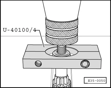
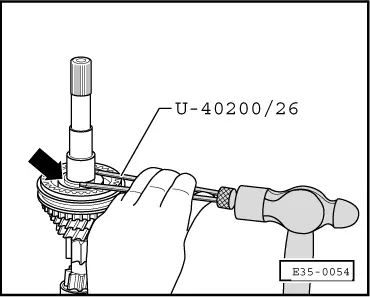
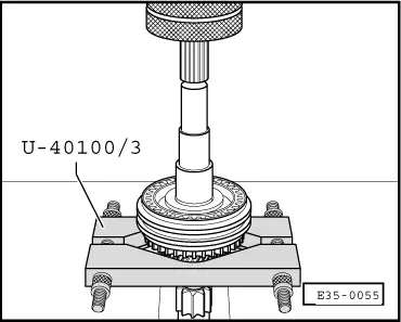
| 5 - | Outer track, roller bearing |
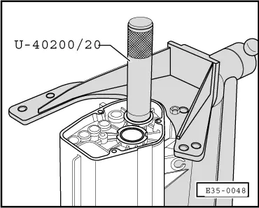
| q | Remove → Fig. |
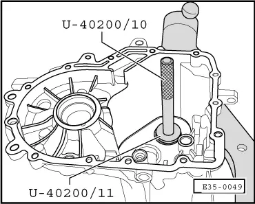
| q | Fitting → Fig. |
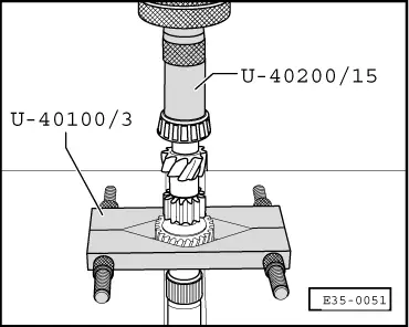
| 6 - | Roller bearings |
| q | Remove → Fig. |
| q | Fitting → Fig. |
| 7 - | Gearbox casing |
| q | In gearboxes manufactured from 07.97, except those bearing the letters DQW, and due to washer → Item the outer track of the roller bearing fits 1 mm lower |
| 8 - | Input shaft |
| q | Adjust → Chapter |
| 9 - | Needle bearing |
| q | Lubricate before fitting |
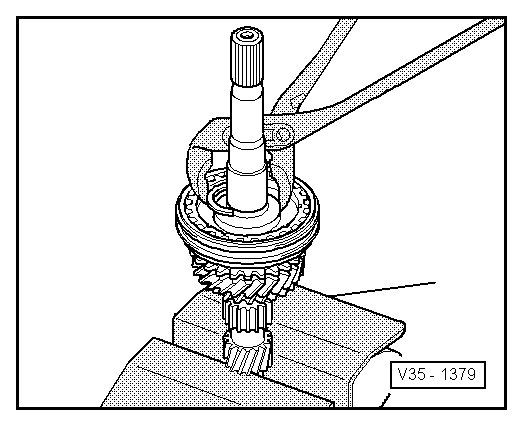
| 10 - | Sliding 3rd gear |
| q | Remove → Fig. |
| q | Fitting → Fig. |
| q | It is fitted together with the sliding sleeve and the 3rd and 4th gear syncromesh hub |
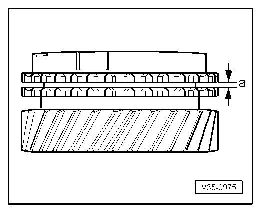
| 11 - | Syncromesh ring 3rd gear |
| q | Checking for wear → Fig. |
| 12 - | Safety ring |
| q | Separation → Fig. |
| q | Location → Fig. |
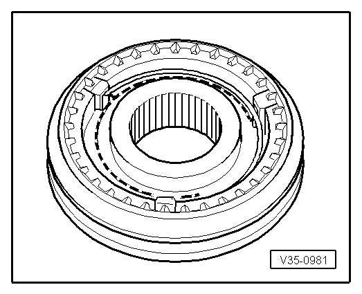
| 13 - | 3rd and 4th syncromesh assembly |
| q | They are matching pairs |
| q | Separation → Fig. |
| q | Assemble → Fig. |
| q | Fitting the input shaft → Fig. |
| 14 - | Safety ring |
| q | Separation → Fig. |
| q | Location → Fig. |
| 15 - | Syncromesh ring 4th gear |
| q | Checking for wear → Fig. |
| 16 - | 4th gear |
| 17 - | Needle bearing |
| q | Lubricate before fitting |
| 18 - | Stop washer |
| 19 - | Roller bearings |
| q | Can be removed without tools |
| 20 - | Shim |
| q | For the input shaft |
| q | Determine thickness → Chapter |
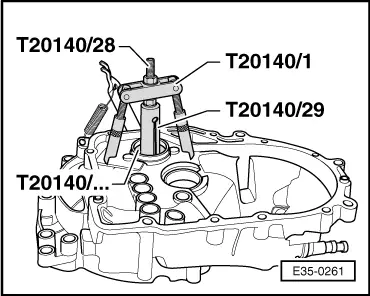
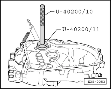
| 21 - | Outer track, roller bearing |
| q | Remove → Fig. |
| q | Fitting → Fig. |
| 22 - | Clutch housing |
| 23 - | Spring |
| q | Fitting position → Fig. |
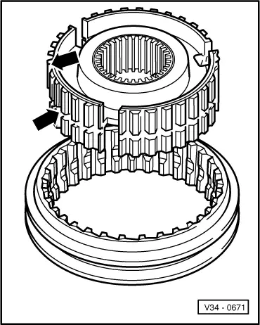
| 24 - | Locking keys |
| 25 - | Sliding sleeve |
| 26 - | Syncromesh hub |
| q | Identiifcation and assembly of hub → Fig. |
| 27 - | Spring |
| q | Fitting position → Fig. |
Note!
|
|
Note!
|
|
|
|
|
|
|
|
|
|
 Caution
|
|
Note!
|
|
|
|
| Syncromesh ring | Measurement “a” on a new syncromesh | Wear limit |
| 3rd and 4th gears | 1.1 to 1.7 mm | 0.5 mm |
|
|
|
|
|
|