| –
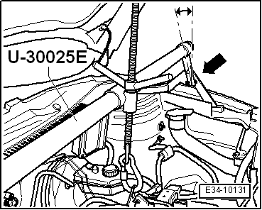
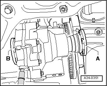
| Adjust properly the bolts from the base -T20145- for the gearbox to have a proper incline when lowering. Feed the right flange shaft -A- through in the area of the flywheel / intermediate plate. |

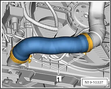
Note | Take care not to damage the power steering lines and coolant lines when lowering gearbox. |
| Install in reverse order to dismantling, noting the following. |
Note | t
| It must be possible to move the clutch plate from side to side on the input shaft. |
| t
| Check whether there are adjusting sleeves in the engine for centring the engine/gearbox assembly and fit if necessary. |
| t
| Ensure that the intermediate plate is correctly seated on the engine. |
| t
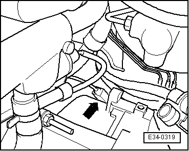
| Note the power steering lines and the clutch mechanism. |
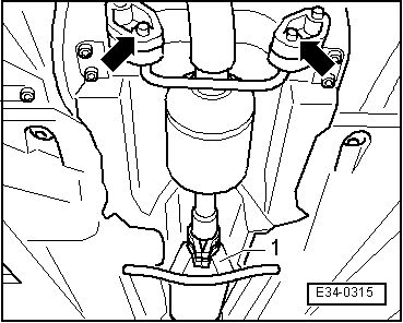
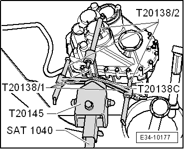
| In order to install the gear it must be on the bracket -T20138C- on thegear box -T20145- and this must be attached on the engine/ gear jack -SAT 1040- |
| –
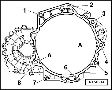
| Adjust the screws of the base -T20145- respectively so that the gearbox is aligned to the guide sleeves. |
| –
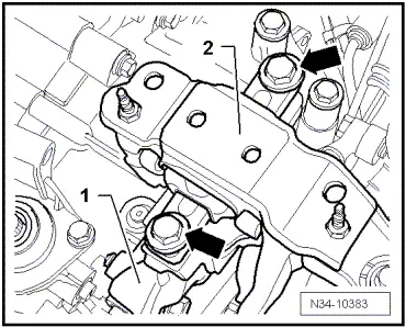
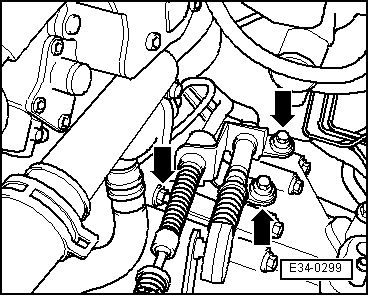
| Include gear with the corresponding screws: Tightening torques → Anchor. |
| –
| Fit the console and the mount of the gearbox bracket. Tightening torques → Rep. Gr.10. |
Note | Once the drive train brackets are fitted, tighten with no strain. |
| –
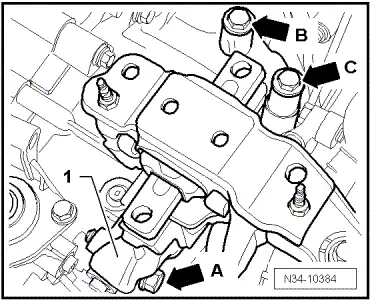
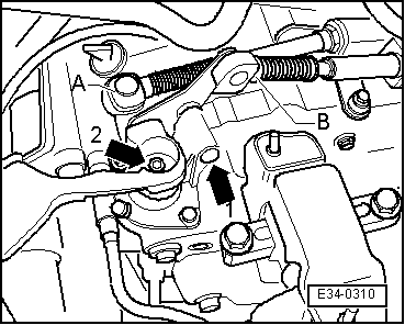
| Fit the starter motor and secure it with the lower bolt. |
Note | t
| Brake fluid is toxic. It should not come into contact with the paintwork due to its corrosive effects. |
| t
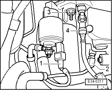
| When handling the brake fluid hoses, place a large protective cover or cloth with no loose threads under the clutch slave cylinder adaptor. |
|
|
|


 WARNING