
Leon Mk1
 Note
Note
|
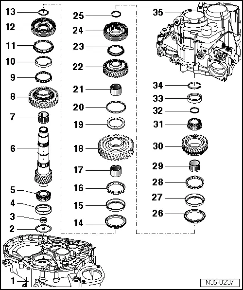
| 1 - | clutch housing |
| 2 - | Oil relay washer |
| 3 - | Dished washer |
| q | Remove → Fig. |
| q | Insertion → Fig. |
| 4 - | Outer ring of roller bearing |
| q | Remove → Fig. |
| q | Insertion → Fig. |
| 5 - | Inner ring of roller bearing |
| q | Releasing → Fig. |
| q | Insertion → Fig. |
| 6 - | Secondary shaft for 1st to 4th gear |
| q | Adjusting → Chapter |
| 7 - | Needle bearing for 2nd gear |
| 8 - | 2nd speed selector gear |
| 9 - | Synchronizer ring (interior ring of the 2nd gear |
| q | Check for wear → Fig. |
| q | Check that the tabs show no signs of wear |
| q | Installation position → Fig. |
| 10 - | Outer ring of 2nd gear |
| q | Replace this if there are grooves or treads caused by wear |
| q | Fit to the synchro ring → Item |
| q | Installation position → Fig. |
| 11 - | 2nd gear synchro-ring |
| q | Check for wear → Fig. |
| q | Installation position → Fig. |
| 12 - | Mobile sleeve/synchroniser body of the 1st and 2nd gear |
| q | Release along with the 2nd gear mobile pinion → Fig. following the removal of the securing ring → Item |
| q | Dismantling → Fig. |
| q | Assembling the mobile element/synchroniser body → Fig. |
| q | Installation position → Fig. |
| q | Driving in |
| 13 - | Securing ring |
| 14 - | 1st gear synchro-ring |
| q | Check for wear → Fig. |
| q | Fit so that the grooves insert on the locking elements of the mobile element → Item |
| 15 - | Outer ring for 1st gear |
| q | Replace this if there are grooves or treads caused by wear |
| q | insert in the synchro ring → Item |
| q | Installation position → Fig. |
| 16 - | Synchronizer ring (interior ring of the 1st gear) |
| q | Check for wear → Fig. |
| q | Check that the tabs show no signs of wear |
| q | Installation position → Fig. |
| 17 - | Needle bearing for 1st gear |
| 18 - | 1st speed selector gear |
| q | Installation position → Fig. |
| 19 - | Thrust ring for the 1st and 4th gear |
| q | 2 Units |
| q | Insert the thrust ring tab into the hole of the secondary shaft |
| 20 - | Washer |
| q | Keep the thrust washers → Item in place on the secondary shaft |
| 21 - | Needle roller bearing for 4th gear |
| 22 - | 4th speed selector gear |
| 23 - | Syncromesh ring for 4th gear |
| q | Check for wear → Fig. |
| 24 - | Mobile sleeve/synchroniser body of the 3rd and 4th gear |
| q | Remove along with the 4th gear mobile pinion → Fig. following the removal of the securing ring → Item |
| q | Dismantling → Fig. |
| q | Installation position of the mobile element/synchromesh body. → Fig. |
| q | Assembling the mobile element / synchroniser body → Fig.and → Fig. |
| q | Insertion → Fig. |
| 25 - | Securing ring |
| 26 - | Synchromesh ring of 3rd gear |
| q | Check for wear → Fig. |
| 27 - | Outer ring for 3rd gear |
| q | Replace this if there are grooves or treads caused by wear |
| q | insert in the synchro ring → Item |
| q | Installation position → Fig. |
| 28 - | Synchro-ring (inner ring for 3rd gear) |
| q | Check for wear → Fig. |
| q | Check that the tabs show no signs of wear |
| q | Installation position → Fig. |
| 29 - | Needle bearing for 3rd gear |
| 30 - | 3rd speed selector gear |
| q | Installation position → Fig. |
| 31 - | Inner ring of roller bearing |
| q | Remove → Fig. |
| q | Insertion → Fig. |
| 32 - | Securing ring |
| q | When the tapered roller bearing → Item or input shaft → Item are renewed, determine thickness of required circlip → Fig. |
| 33 - | Outer ring of roller bearing |
| q | Remove → Fig. |
| q | Insertion → Fig. |
| 34 - | Shim |
| q | Determine thickness → Chapter |
| 35 - | Gearbox |