
Leon Mk1
| Gear selection mechanism: removing and fitting |
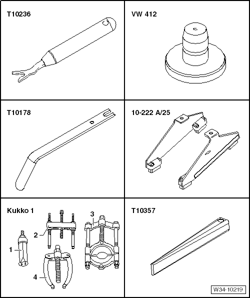
| Special tools and workshop equipment required |
| t | Assembly tool -T10236- |
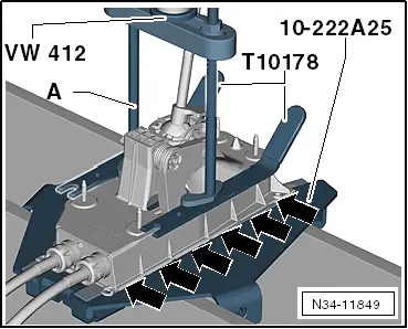
| t | Die -VW 412- |
| t | Installation tool -T10178- |
| t | Adapter -10 - 222 A /25- |
| t | 2 = Counter-support, e.g. -Kukko Baureihe 16- |
| t | Wedge -T10357- |
|
|
|
|
|
|
|
|
|
|
|
 Caution
|
|
|
|
|
|
|
|
|
|
|
|
|
|