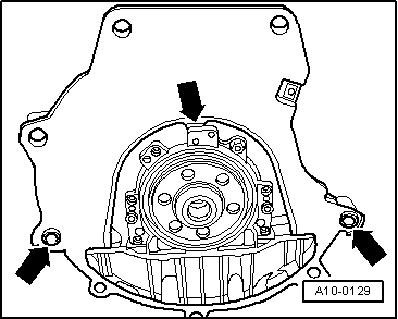
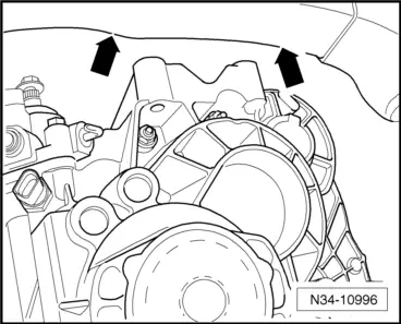
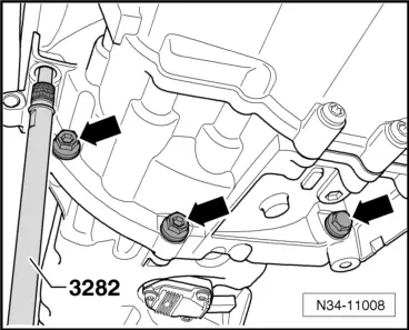
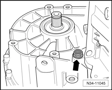
seat Workshop Repair Guides

SEAT Leon Workshop & Auto Repair Manuals

Torque settings > < Removing gearbox
Installing gearbox
Installing gearbox
  Note
t  Refer to procedure „Removing gearbox“ for required special tools → Chapter.
t  Always renew self locking nuts and bolts
t  Renew bolts which must be tightened further to a torque angle.
t  All cable ties which were opened or cut during removal must be renewed at the same points.
t  Clean the input shaft splines and in the case of used clutch plates, the hub splines. Remove corrosion and apply only a very thin coating of grease for clutch plate splines -G 000 100- to the splines of the input shaft. Then move clutch plate to and fro on input shaft until hub moves freely on shaft. Remove excessive grease.
–  All threaded holes into which self-locking bolts are to be screwed must be cleaned of residual locking fluid carefully with a thread tap.
–  Check if the centring sleeves are installed in the engine for the purpose of centring the engine with the gearbox and insert these if they are not installed.
If dowel sleeves are not fitted, difficulties shifting gears, clutch problems and possible noises from the gearbox (rattling of gears which are not engaged) could occur.
   
–  Ensure that intermediate plate is hooked into sealing flange and pushed onto dowel sleeves -arrows-.
–  Check release bearing for wear; if necessary, renew slave cylinder with release bearing → Chapter.
–  Move engine assembly onto the engine and gearbox jack -SAT 1040- and put it in installation position.
–  Now tilt the gearbox to the left over the counterhold -T20138C- protection sleeve.
  A10-0129
–  Then carefully raise gearbox further, observing longitudinal member.
  Note
When installing the gearbox, do not damage the pipes and lines.
–  Align the gearbox to the engine and fit.
  N34-10996
–  Screw in lower bolts that fix the engine to the gearbox and tighten to the corresponding tightening torque → Chapter.
  N34-11008
–  Screw in engine/gearbox connecting bolt -arrow- and tighten to specified torque → Chapter.
–  Once the gearbox is screwed to the engine underneath, remove the gearbox support -T20138C- from the gearbox.
–  Centre engine assembly so as to bring it to the correct installation position. To do this, lift until gearbox is fully in contact with left engine/gearbox mounting.
  N34-11045
–  Screw in new hexagon bolts -arrows- for left engine/gearbox mounting and tighten to specified torque → Chapter.
  WARNING
First remove the engine mounting -U30025F- once all engine assembly bracket bolts have been tightened to the corresponding tightening torque.
  N34-10991
–  Screw in upper engine/gearbox securing bolts -arrows- and tighten to specified torque → Chapter.
  N34-11006
–  Install starter -3- → Electrical system; Rep. gr.27.
–  Connect electrical connection -2- on the reverse light switch -F4-.
Attach earth strap -1- to gearbox → Chapter.
  N34-11001
–  If a retainer -1- is installed, secure earth strap with a nut -2-.
  N34-11067
–  Gearboxes for vehicles with start-stop system: connect connector of -gearbox neutral position sender-arrow -G701-.
  N34-11705
–  Renew retaining ring -arrow A- and O-ring -arrow B- on stub shafts.
Lubricate splines of stub shafts using grease -G 000 100-.
Then install drive shafts → Running gear, axles, steering; Rep. gr.40.
  N34-10112
–  Install drive shaft heat shield, if present -arrows- → Running gear, axles, steering; Rep. gr.40.
  N34-11369
–  Install pendulum support → Running gear, axles, steering; Rep. gr.40.
–  Reassemble exhaust system → Rep. gr.26
  N34-10973
–  If front left vehicle level sender -G78- is present, install it → Rep. gr.40.
  N34-11241
–  Install cowling -arrow- together with radiator fans → Rep. gr.19.
  N34-11165
–  Fit charge air hoses -arrow 1- and -arrow 2- and, if removed, charge air pipe on engine → Rep. gr.21.
  N34-10733
–  Remove sealing tool -T10249/1- from supply hose leading to the clutch master cylinder.
  Note
The hose clamps -3094- that appear in the figure can be ignored.
  N30-10217
–  Push pipe/hose line or pipe line -A- to stop into slave cylinder breather and press down clip -arrow-.
–  Test line by tugging on it.
–  Fold back the supply hose to its original form as required.
–  Bleed clutch system → Chapter.
–  Check for correct installation position of vacuum hose for brake system, install vacuum hose if necessary → Rep. gr.47.
  N34-10997
–  Install cable support bracket on gearbox and tighten bolts -arrows- to specified torque → Item.
  N34-10915
–  Fit gearbox selector lever -2- → Item and tighten securing nuts to specified torque → Item.
–  Spread a small amount of grease on pin -arrow- of gearbox selector lever -2-.
Allocate grease using → Electronic parts catalogue (ETKA).
–  Mount gear selector cable; renew securing clip -1- each time it is removed.
–  Install relay lever together with cable end-piece → Fig..
–  Adjust selector mechanism → Chapter
–  Install battery tray and battery → Electrical system; Rep. gr.27
–  Install the complete air filter housing, if previously removed → Rep. gr.23.
–  If necessary, install engine cover.
–  Connect battery and follow procedure after connecting battery → Electrical system; Rep. gr.27.
–  Mount plenum chamber cover → Body; Rep. gr.50
–  Mount windscreen wiper arms → Electrical system; Rep. gr.92.
–  Check gearbox oil level → Chapter .
–  Secure front left wheel housing liner → General body repairs, exterior; Rep. gr.66.
–  Install noise insulation → General body repairs, exterior; Rep. gr.50.
–  Install wheels → Running gear, axles, steering; Rep. gr.44.
–  For vehicles with front sender for vehicle level, check headlight adjustment → Electrical system; Rep. gr.94.
  N34-10951

Torque settings > < Removing gearbox