seat Workshop Repair Guides

SEAT Workshop Service and Repair Manuals

Fault table > < Gearbox: Electrical check
Automatic gearbox 099 4-speed self-diagnosis
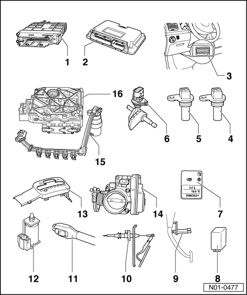
Locations of electrical/electronic components
 
N01-0477
  • Automatic gearbox control unit -J217-
    • ◆ Location => Fig.1
    • ◆ Removing => Fig. 2
    • ◆ Installing => Fig. 3
    • ◆ Checked by self-diagnosis => Carrying out self-diagnosis, Page 01-31
    • ◆ Control unit exchanges information via data bus on vehicles equipped with data bus
 
N01-0477
  • Engine control unit
    • ◆ Location for vehicles to 05.00 => Fig. 4
    • ◆ Location for vehicles from 06.00 => Fig. 5
    • ◆ Removing and installing

=> Repair group 23; of the respective engine code

=> Repair group 24; of the respective engine code

If engine or gearbox control units are replaced, the system must be brought to basic setting , Initiating basic setting.

    • ◆ Control unit exchanges information via data bus on vehicles equipped with data bus
  • Diagnostic connection
    • ◆ Location for vehicles to 05.00 => Fig. 6
    • ◆ Location for vehicles from 06.00 => Fig. 7
 
N01-0477
  • Road speed sender -G68-
    • ◆ Location: on gearbox
    • ◆ Checked by self-diagnosis
    • ◆ Removing and installing

=> Automatic gearbox 099 - 4-speed; Repair group 38; Dismantling and assembling parking lock

  • Gearbox speed sender -G38-
    • ◆ Location: on gearbox
    • ◆ Removing and installing

=> Automatic gearbox 099 - 4-speed; Repair group 38; Dismantling and assembling parking lock

    • ◆ Checked by self-diagnosis

Do not interchange connector T2 for senders -G38- and -G68-

 
N01-0477
  • Multifunction switch -F125-
    • ◆ Removing and installing

=> Automatic gearbox 099 - 4-speed; Repair group 38; Dismantling and assembling parking lock

    • ◆ Checked by self-diagnosis
  • Selector lever position display -Y6-
    • ◆ Location => Fig.14
  • Relay for starter lock-out and reversing light -J226-
    • ◆ Location for vehicles to 05.00 => Fig.12
    • ◆ Location for vehicles from 06.00 => Fig. 13
  • Brake light switch -F-
    • ◆ Location and removing and installing =>Fig. 9
    • ◆ Can be checked electrically => page 01-58
 
N01-0477
  • Kickdown switch -F8-
    • ◆ Location for vehicles without EPC => Fig.10
    • ◆ Location for vehicles with EPC => Fig. 11
    • ◆ Can be checked electrically => page 01-58
  • Cruise control switch -E45-
    • ◆ Location => Fig. 8
    • ◆ Removing and installing

=> Electrical system; Repair group 94; Steering column switch; Servicing steering column switch

    • ◆ Can be checked by reading measured value block
      => Page 01-58
 
N01-0477
  • Solenoid for selector lever lock -N110-
    • ◆ Location and removing and installing

=> Automatic gearbox 099 - 4-speed; Repair group 37; Servicing selector mechanism for vehicles from 06.00; Removing and installing selector lever lock solenoid -N110-

    • ◆ The solenoid is checked by self-diagnosis
    • ◆ Can be checked in measured value block => page 01-89
  • Tiptronic switch -F189-
    • ◆ Location => Fig. 15
    • ◆ Can be checked during the electrical check => Page 01-89
  • Throttle valve potentiometer -G69-, or accelerator position sender -G79-
    • ◆ Location and further information => Fig. 16
 
N01-0477
  • Conductor strip with integrated gearbox oil temperature sender (ATF) -G93-
    • ◆ Location: on valve chest
    • ◆ -G93- is checked by self-diagnosis
  • Valve chest
    • ◆ Location: on gearbox

=> Automatic gearbox 099 - 4-speed; Repair group 38; Removing and installing valve chest

    • ◆ The solenoid valves -N88-, -N89-, -N90-, -N91-, -N92-, -N93-, -N281-, -N282- and -N283- are attached to the valve chest
    • ◆ The valves are checked by self-diagnosis
 
N37-0286

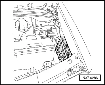
→ Fig.1    Location of automatic gearbox control unit -J217-

The control unit is located in the engine compartment, left.

 
N37-0288

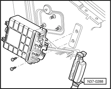
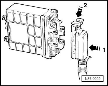
→ Fig.2    Removing automatic gearbox control unit -J217-

  • ‒ Release multi-pin connector, then pull connector off control unit.
  • ‒ Remove control unit.
 
N37-0292

→ Fig.3    Installing automatic gearbox control unit -J217-

  • ‒ Fit multi-pin connector onto control unit -J217- pins -1- then lock multi-pin connector -2-.
 
N01-0138

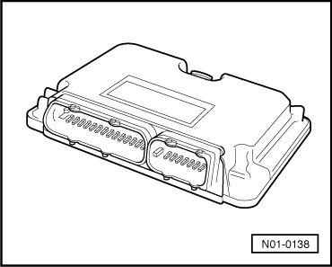
→ Fig.4    Engine control unit for vehicles to 05.00

Location: The control unit is located behind dash panel.

Removing and installing control unit

=> Repair group 23; of the respective engine code

=> Repair group 24; of the respective engine code

 
N01-0491

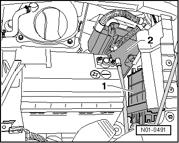
→ Fig.5    Engine control unit for vehicles from 06.00

Location: The control unit -2- is located in engine compartment, left.

Removing and installing control unit

=> Repair group 23; of the respective engine code

=> Repair group 24; of the respective engine code

 
N37-0293

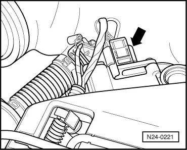
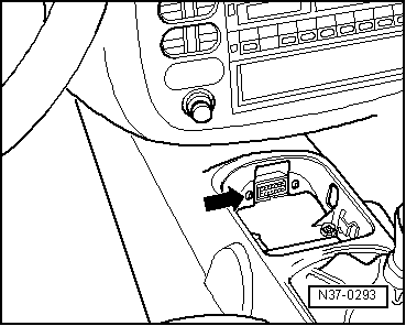
→ Fig.6    Diagnostic connection for vehicles to 05.00

Location: The diagnostic connection -arrow- is located in centre console.

  • ‒ Lever cover or ashtray housing out from centre console.

 
N01-0476

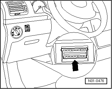
→ Fig.7    Diagnostic connection for vehicles from 06.00

Location: The diagnostic connection -arrow- is located under stowage compartment on driver's side.

 
N37-0285

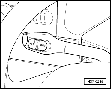
→ Fig.8    Cruise control system switch -E45-

Location: Cruise control switch is located on steering column switch.

Removing and installing cruise control switch

=> Electrical system; Repair group 94; Steering column switch; Servicing steering column switch

 
N37-0520

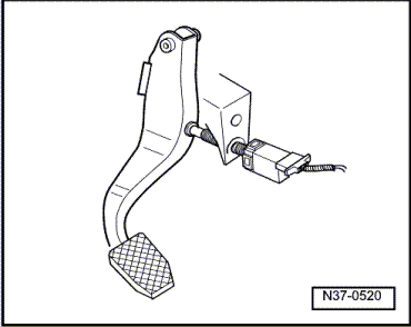
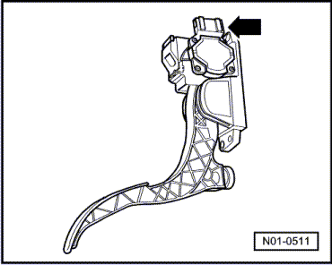
→ Fig.9    Brake light switch -F-

Location: Brake light switch (arrow) is located on pedal cluster.

Removing and installing brake light switch

=> Brake system; Repair group 46; Brake pedal - Assembly overview; Removing and installing brake pedal

 
N37-0154

→ Fig.10    Kickdown switch -F8- for vehicles without EPC

Location: Kickdown switch (arrow) is integrated into accelerator cable and is located on bulkhead in engine compartment.

Removing and installing kickdown switch

  • ‒ First remove the accelerator cable. Remove and install the kickdown switch. Then reinstall cable and adjust.

=> Repair group 20; Adjusting accelerator cable

 
N01-0511

→ Fig.11    Kickdown switch -F8- for vehicles with EPC

Location: Kickdown switch (arrow) is integrated into accelerator pedal position sender.

Removing and installing kickdown switch

  • ‒ Servicing accelerator mechanism.

=> Repair group 20; Servicing accelerator mechanism.

 
N01-0078

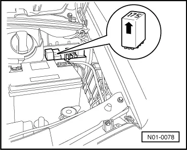
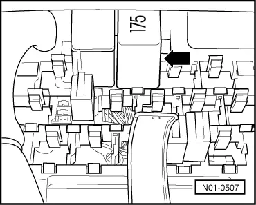
→ Fig.12    Relay for starter inhibitor and reversing light -J226- for vehicles to 05.00

Location: Relay located on relay carrier in engine compartment, left.

Relay is marked with number "175" -arrow-.

 
N01-0507

→ Fig.13    Relay for starter inhibitor and reversing light -J226- for vehicles from 06.00

Location: Relay located on relay carrier behind stowage compartment on driver's side.

Relay is marked with number "175" -arrow-.

 
N01-0509

→ Fig.14    Selector lever position display -Y6-

Vehicles to 05.00

Location: In dash panel insert

Removing and installing selector lever position display

=> Electrical system; Repair group 90; Dash panel insert for vehicles ▸ 05.00; Removing and installing dash panel insert

Vehicles from 06.00

Location: In dash panel insert with diagnostic interface for data bus -J533-

Removing and installing selector lever position display

=> Electrical system; Repair group 90; Dash panel insert for vehicles 06.00▸; Removing and installing dash panel insert

 
N01-0514

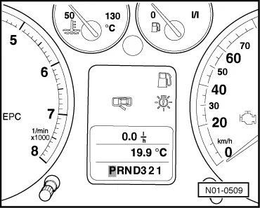
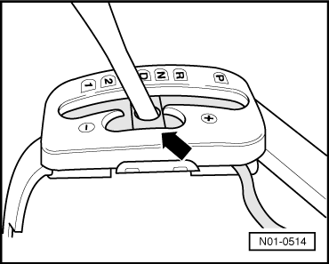
→ Fig.15    Tiptronic switch -F189-

  • ◆ Location: switch is part of printed circuit board which is located in selector mechanism cover.
  • ◆ It consists of 3 Hall sensors which are actuated by solenoids.
  • ◆ The switch can be tested during the electrical check => Page 01-89
  • ◆ In case of defect, the symbol insert must be renewed with the printed circuit board.

=> Automatic gearbox 099 - 4-speed; Repair group 37; Servicing selector mechanism for vehicles from 06.00; Dismantling and assembling selector mechanism

 
N24-0221

→ Fig.16    Throttle valve potentiometer -G69- or throttle position sender -G79-

Locations:

The potentiometer is part of the throttle valve control part -J338- (arrow). It is located on the throttle valve housing (engine).

The throttle position sender -G79- is part of the electronic power control (EPC) and can be found on the foot pedal.

For self-diagnosis:

The signal from the throttle valve potentiometer indicates the position of the accelerator.

The signal from the throttle position sender gives the same information.

Both signals (messages) are sent to the engine control unit.

The engine control unit relays the signal to the gearbox control unit.

On vehicles with data bus, the signal comes from the bus. On these vehicles, the data bus interface is checked in addition.

The self-diagnosis of the automatic gearbox only checks the signal, not the potentiometer! Additionally the wire for the signal is also checked on vehicles without data bus.

The signal can only be read-out in measured value block.

=> Read measured value block ; Display group number 001

The self-diagnosis of the engine control unit should therefore always be performed when self-diagnosis indicates that this signal is faulty.

Checking and adjusting or removing and installing throttle valve potentiometer

=> Repair group 24; depending on engine code

Fault table > < Gearbox: Electrical check