seat Workshop Repair Guides

SEAT Workshop Service and Repair Manuals

Transporting and securing gearbox to assembly stand > < Gearbox: removing
Gearbox: fitting
Gearbox: fitting
Perform the assembly operations in reverse order to those described for the disassembly, taking the following into account:
–  Install the torque converter → Chapter
–  Ensure that the torque converter is correctly positioned and securely fastened to the retaining tool -T20155-.
  Note
While carrying out repairs, the converter should not slip out of position.
   
–  Before assembly ensure the correct positioning of the centering fittings between the engine and the gearbox.
–  When installing the gearbox, ensure that the converter's threaded pins coincide with the bolt holes of the flywheel.
–  Bring the gearbox closer to the engine, using the spindles of the support -T20138B-, and position the gearbox until it is in the correct location.
–  Mount the left hand side drive shaft. → Running gear, axles, steering; Repair group. 40; Drive shafts. removing and fitting.
  N37-0944
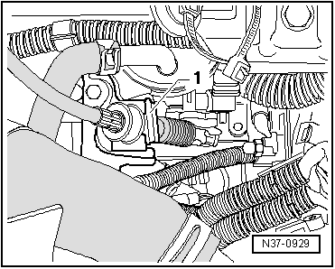
–  Always replace the axle catch - 1- for the selector lever cable.
–  Check the selector lever cable adjustment → Chapter.
–  Check the multifunction switch adjustment; and if necessary, adjust → Fig.
–  Check the ATF level and top up: with the filler tube → Chapter, without the filler tube → Chapter
–  Fill cooling system . → Rep. Gr.19
–  Check the connectors of all the electrical connections (visually).
–  Check the gear selection mechanism → Chapter.
–  After connecting the battery, depending on the version, vehicle equipment will have to be encoded (encoding the radio, adjusting the clock, etc.).
After assembly:
–  Begin basic adjustment: → VAS 5051, Vehicle self-diagnosis.
Tightening torques
  N37-0929
Gearbox to engine
  N37-0943
PositionBoltAmountTorque (Nm)
1M12×65280
2M10×75145
3M7×12215
4M12×70180
5M8×35125
6M8×35125
7M8×35125

A: Adjustment bushes for centring the gearbox.
   
Torque converter to flywheel
Always replace the nuts
60 Nm
Pendulum support to the subframe
Always replace the bolts
40 Nm
Pendulum support to the gearbox
Always replace the bolts
30 Nm

   
Console attachment
Always replace the bolts
40 Nm + 90°
Console attachment to engine
Always replace the bolts
40 Nm + 90°
Drive shaft to the articulation flange on the gearbox (diagonally in two stages)
M8
M10
Always replace the bolts
20 Nm + 90°
50 Nm + 45°
Drive shaft /wheel hub nut
Always replace nut
50 Nm
Wheel bolts120 Nm


Transporting and securing gearbox to assembly stand > < Gearbox: removing