
Leon Mk1
|
|
|
|
|
|
|
|
|
|
|
|
|
|

|
 Note
Note
|
|
|
|
|
|
 Caution
|
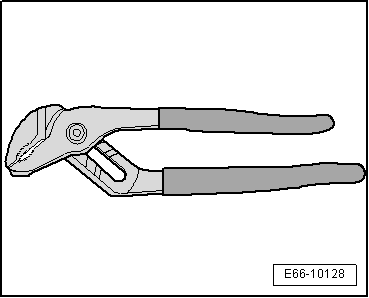
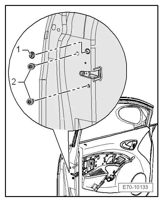
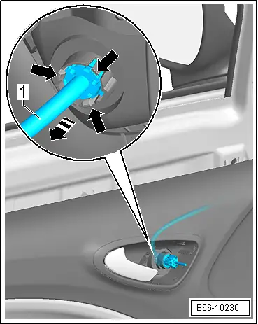
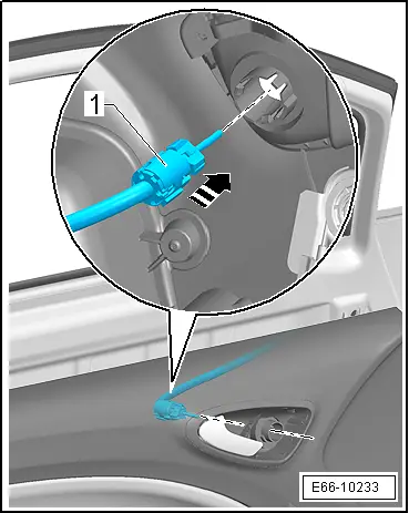
| – | Loosen the fastening nut -1- using ratchet pliers until the strain on the spring is released -2-, (do not fully remove the fastening nut). |
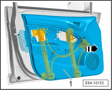
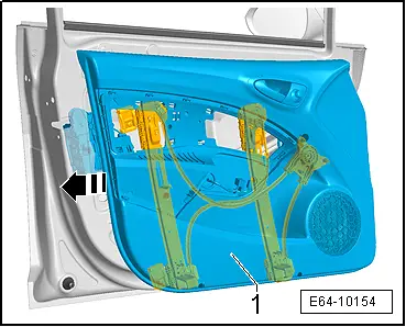
| – | Fold the wing mirror -1- in the direction of the -arrow-. |
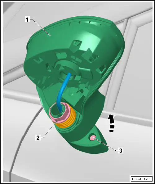
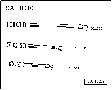
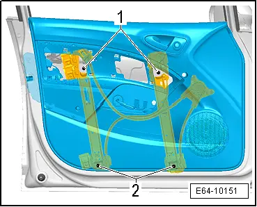
| – | Undo the screws -3- on the holder of the exterior mirror using the torque wrench set -SAT 8010- (do not screw out the screws completely). |
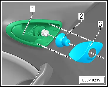
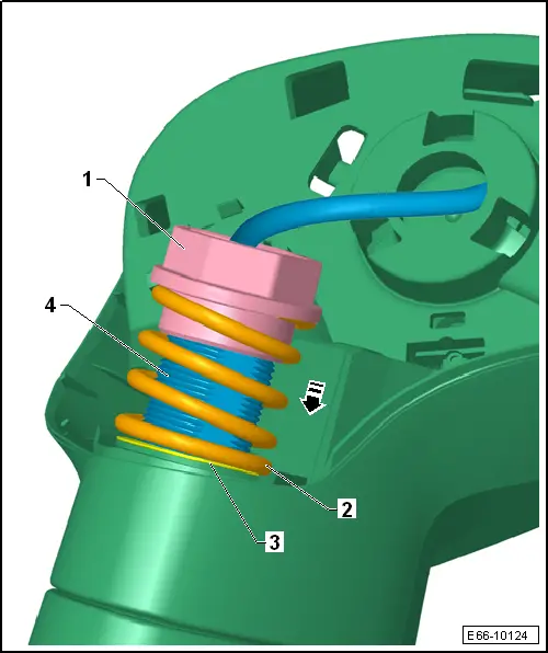
| – | Remove the nut -1-, the spring -2- and the washers -3-. |
Note| The following differences should be noted depending upon the wing mirror removed: |
| Right wing mirror |
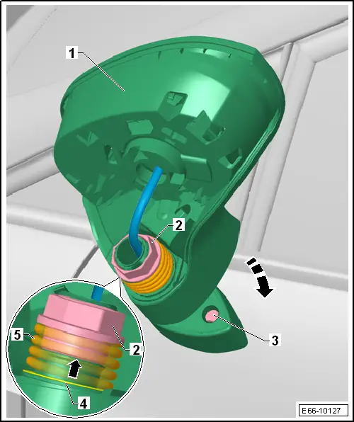
| – | Press the axis -4- downwards in the direction of the -arrow- approximately 10 mm and gently turn 30° clockwise. |
| Left wing mirror |
| – | Press the axis -4- downwards in the direction of the -arrow- approximately 10 mm and gently turn 30° counter-clockwise. |
| Proceed as follows for both wing mirrors |
| – | Remove wing mirror from door. |
|
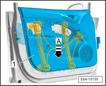
| – | The base of the wing mirror should be lowered as shown in the diagram. |

| – | The tabs -3- on the shaft -1- should be on the limiters -2- on the base of the wing mirror support. |
| – | On the upper part, place the washers → Item, the spring → Itemand the heptagonal nut → Item. |
| – | Tighten the fastening nut by hand until the spring is tensioned. |
Note| The base of the wing mirror should be lowered as shown in the diagram until it is inserted in the door support. |
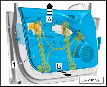
| – | Before mounting the wing mirror on the door reinforcement, insert the operation mechanism through the shaft opening → Item. |
| – | Tighten bolt -3- to a torque of 10 Nm. |
| – | Unfold the wing mirror -1- in the direction of the -arrow-. |
Caution
|
| – | Tighten the fastening nut -2- using a pair of ratchet pliers until the lower limit of the nut is touching the base of the shaft -arrow-. |
|
|
|
|
|
|
|
|

|
|
|
|
|
|
|