seat Workshop Repair Guides

SEAT Workshop Service and Repair Manuals

Enginecrankshaft group, pistons > < Technical data
4-cyl. injection engine (2 valve without intermediate shaft), Mechanics
Removing and installing engine
Notes on removing
  • ‒ The engine is removed downwards together with the gearbox.
  • ‒ All cable ties which are opened or cut open when removing engine, must be replaced in the same position when installing engine.
  • ‒ Remove engine cover.

Note:

Check whether a coded radio is installed as during the forthcoming work sequences the battery earth strap must be disconnected. Obtain radio code first if necessary.

 
N40-0109
  • ‒ With the ignition switched off disconnect battery earth strap.
  • ‒ Remove battery.
  • ‒ → Remove air guide trim -1-.
  • ‒ Unbolt battery trim -2- with coolant expansion tank and lay to side without opening cooling system.
 
N10-0276
  • ‒ In preparation for further dismantling work, disconnect the connectors -arrows- behind the battery.
  • ‒ Remove battery tray.
  • ‒ Pull off or disconnect all other electrical connections as necessary from engine and body and lay to one side.
  • ‒ Remove air cleaner with intake hose:

=> Repair group 24; Servicing injection system; Dismantling and assembling air cleaner.

Warning!
Fuel supply system is under pressure! Before loosening hose connection wrap a cloth around the connection. Then release pressure by carefully pulling hose off connection.

 
N10-0256
  • ‒ → Pull off supply pipe/hose -1- (with white marking) and return pipe/hose -2- (with blue marking) and collect fuel that leaks out with a cloth.
  • ‒ Seal the pipes so that the fuel system is not contaminated by dirt etc.
  • ‒ Observe rules for cleanliness .
  • ‒ Pull vacuum and breather hoses off engine.
  • ‒ Remove noise insulation tray.

Vehicles with manual gearbox

  • ‒ Pull pipe/hose off slave cylinder on gearbox and lay to one side.

=> 6-speed manual gearbox 02N; Repair group 30; Assembly overview - Hydraulics and clutch release mechanism

  • ‒ Remove operating cable from gearbox:

=> 6-speed manual gearbox 02N; Repair group 34; Servicing selector mechanism; Removing and installing operating cables

  • ‒ Remove drive shafts:

=> Running gear, Axles, Steering; Repair group 40; Removing and installing drive shaft

Vehicles with automatic gearbox

  • ‒ Remove selector lever cable from gearbox:

=> Automatic gearbox 099; Repair group 37; Servicing selector mechanism; Dismantling and assembling selector mechanism

  • ‒ Unbolt drive shafts at gearbox flanged shaft and tie up.

=> Running gear, Axles, Steering; Repair group 40; Removing and installing drive shaft

Vehicles with air conditioner

  • ‒ Observe additional information and removal instructions => Page 10-17.

Continuation for all vehicles

  • ‒ Remove ribbed belt => Page 13-11.
  • ‒ Remove power assisted steering vane pump with bracket and lay to side; hoses remain connected.

=> Running gear, Axles, Steering; Repair group 48; Assembly overview: vane pump, reservoir, hydraulic pipes

  • ‒ Unbolt P.A.S. hydraulic pipe at right engine bracket.
  • ‒ Remove front exhaust pipe => Page 26-2, exhaust manifold, front exhaust pipe and catalyst with attachments.
  • ‒ Drain coolant => Page 19-13.
  • ‒ Pull connectors off thermo-switch and radiator fan.
  • ‒ Pull radiator coolant hoses off engine using spring-type clip pliers V.A.G 1921 or VAS 5024.
  • ‒ Bring lock carrier into service position:

=> General body repairs, Exterior; Repair group 50; Body front; lock carrier service position

  • ‒ Insert engine bracket T 10012 in engine/gearbox jack V.A.G 1383 A.
 
N10-0056
  • ‒ → Attach engine bracket T 10012 with securing bolt M10 X 25/ 8.8 to cylinder block and tighten to 40 Nm.
  • ‒ Tighten securing bolt on exhaust side by hand.
  • ‒ Lift engine and gearbox lightly using engine/gearbox jack V.A.G 1383 A.
  • ‒ Remove pendulum support.

=> Running gear, Axles, Steering; Repair group 40; Servicing front wheel suspension; I - Assembly overview, subframe, anti-roll bar, wishbone

 
N10-0040
  • ‒ → Unbolt assembly mounting, right securing bolts -1-.

 
N10-0259
  • ‒ → Unbolt securing bolts and nuts on left of subframe -arrows-.

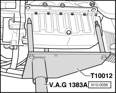
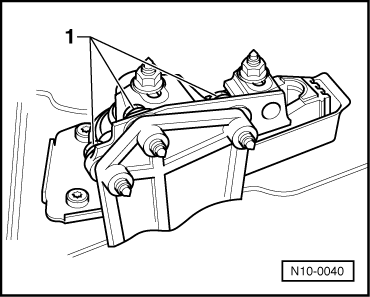
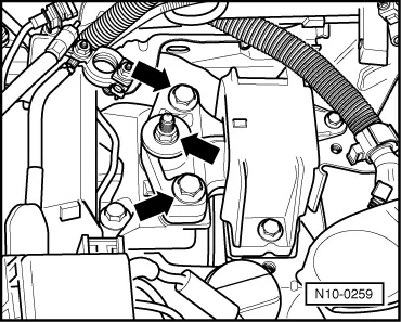
Note:

To remove securing bolts use ladder VAS 5085.

  • ‒ Carefully lower engine with gearbox.

Note:

Engine and gearbox must be guided carefully when lowering to prevent damage to the bodywork, hoses and wiring.

Enginecrankshaft group, pistons > < Technical data