seat Workshop Repair Guides

SEAT Workshop Service and Repair Manuals

4-Cyl. injection engine (2 valve), Mechanics > < Exhaust gas recirculation system
6-cyl. fuel injection engine, Mechanics
Exhaust gas recirculation system
Checking exhaust gas recirculation valve with temperature sensor

Special tools, testers and auxiliary items

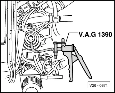
  • ◆ Hand vacuum pump V.A.G 1390
  • ◆ Fault reader V.A.G 1551 or vehicle system tester V.A.G 1552 with cable V.A.G 1551/3
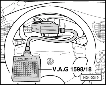
  • ◆ Test box V.A.G 1598/18
  • ◆ Hand multimeter V.A.G 1526 or multimeter V.A.G 1715
  • ◆ Adapter set V.A.G 1594
  • ◆ Current flow diagram

Check conditions

  • ● Vacuum pipes and hose connections free of leaks.
  • ● Vacuum pipes not blocked/kinked.
  • ● Engine oil temperature at least 50 °C

Test sequence

  • ‒ Connect fault reader V.A.G 1551 (V.A.G 1552) and select engine electronics control unit (address word 01); carry out selection at idling:

=> Repair group 01; Self-diagnosis; Connecting fault reader V.A.G 1551 and selecting engine electronics control unit

 
→ Indicated on display:
Rapid data transfer    HELP
Select function XX
  • ‒ Input 08 for "Read measured value block" function and confirm with Q.
 
→ Indicated on display:
Read measured value block    HELP
Input display group number XX
  • ‒ Input 01 for "Display group number" and confirm with Q.
 
→ Indicated on display:
(1...4 = Display zones)
Read measured value block    1    ⇒
    1    2    3    4

Only continue with the test when

  • ● The coolant temperature is above 50 °C
    -Display zone 2-
  • ‒ Press C key.
  • ‒ Input 02 for "Display group number" and confirm with Q.
 
→ Indicated on display:
(1...4 = Display zones)
Read measuring value block 2    ⇒
    1    2    3    4
  • ‒ Read off figure displayed in display zone 4.
        Specification: EGRn. active
        (exhaust gas recirculation system not active)
  • ‒ Increase engine speed.
  • ‒ Read off figure displayed in display zone 4.
        Specification: EGR active
        (exhaust gas recirculation system active)
  • ‒ Pull vacuum hose off (mechanical) exhaust gas recirculation valve.
 
V26-0871
  • ‒ → Connect hand vacuum pump V.A.G 1390 to valve with aux. hose.
  • ‒ Operate pump.
        The idling characteristics must noticeably
         deteriorate.

If the idling characteristics do not deteriorate:

  • ‒ Press ⇒ button.
  • ‒ Input 06 for "End output" and confirm with Q.
  • ‒ Switch off ignition
  • ‒ Check pipes and connections for blocking, clean, if necessary replace exhaust gas recirculation valve.
  • ‒ Check activation of exhaust gas recirculation valve (N18):

=> Repair group 01; Self-diagnosis; Final control diagnosis

 
N24-0219

Exhaust gas recirculation valve clicks during the final control diagnosis:

  • ‒ Check wiring to exhaust gas recirculation valve temperature sensor (G98):
  • ‒ Remove dash panel insert:

=> Electrical system; Repair group 90

  • ‒ → Connect test box V.A.G 1598/18 to control unit wiring loom.

 
N26-0098
  • ‒ → Separate 2 pin connector to exhaust gas recirculation system temperature sensor -arrow-.
 
N24-0231
  • ‒ Check wiring between test box and 2 pin connector for open circuit according to current flow diagram.
        Contact 1+socket 15
        Contact 2+socket 33
        Wire resistance: Max. 1.5 ω
  • ‒ → Check wiring at 2 pin connector for short to one another.
        Contact 1+socket 33
        Contact 2+socket 15
        Specification: ∞ω

If the specifications are attained:

  • ‒ Replace exhaust gas recirculation temperature sensor (G98).
  • ‒ Interrogate fault memory:

=> Repair group 01; Self-diagnosis; Interrogating fault memory

4-Cyl. injection engine (2 valve), Mechanics > < Exhaust gas recirculation system