seat Workshop Repair Guides

SEAT Workshop Service and Repair Manuals

Checking knock sensors > < Test data, spark plugs
Motronic injection and ignition system
Checking Hall sender

Special tools, testers, measuring instruments and auxiliary items required

  • ◆ Test box V.A.G 1598/18
  • ◆ Hand multimeter V.A.G 1526 or multimeter V.A.G 1715
  • ◆ Adapter set V.A.G 1594
  • ◆ Current flow diagram

Test conditions

  • ● Battery voltage at least 11.5 V

Test sequence

 
N10-0017
  • ‒ → Remove ignition cables off ignition transformer and remove cable duct -2-.
 
N28-0025
  • ‒ → Pull 3 pin connector off Hall sender -arrow-.

 
V28-1074
  • ‒ → Check voltage between contacts 1+3 of detached connector.
  • ‒ Switch on ignition.
        Specification: Min. 11.5 V
  • ‒ Switch off ignition
  • ‒ Remove dash panel insert:

=> Electrical system; Repair group 90

 
N24-0219
  • ‒ → Connect test box V.A.G 1598/18 to control unit wiring loom.

 
V28-1074
  • ‒ → Check wiring between test box and 3 pin connector for open circuit according to current flow diagram.
        Contact 1+socket 23
        Contact 2+socket 44
        Contact 3+socket 56
        Wire resistance: Max. 1.5 ω
  • ‒ Additionally check wires for short to one another.
        Contact 3+socket 44
        Contact 3+socket 23
        Contact 2+socket 23
        Specification: ∞ω

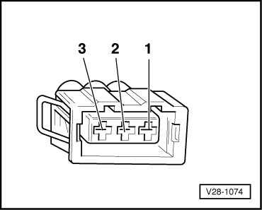
If no wiring fault is detected and voltage was present between contacts 1+3:

  • ‒ Renew Hall sender (G40)
    , item 1.

If no wiring fault is detected and no voltage was present between contacts 1+3:

  • ‒ Renew Motronic control unit (J220)
    => Page 24-8, item 2.

Checking knock sensors > < Test data, spark plugs