|
Evaluating measured value blocks, display groups 0...13
Evaluating measured value blocks, display groups 0...13
|
|
|---|
|
Display group 00 (decimal displayed value)
|
|
▪ Engine running at idling speed
|
|
Read measured value block 0
|
◂ Indicated on display
|
|
|
|
x
|
x
|
x
|
x
|
x
|
x
|
x
|
x
|
x
|
x
|
|
|
|
|
1
|
2
|
3
|
4
|
5
|
6
|
7
|
8
|
9
|
10
|
◂ Display zones
|
Specification
|
Corresponds to
|
|
|
|
|
|
|
|
|
|
|
|
Lambda learnt value at part throttle (multiplicative)
|
118...138
|
-8...8 %
|
|
|
|
|
|
|
|
|
|
|
Lambda learnt value at idling
(additive)
|
115...141
|
-0.64...0.64 ms
|
|
|
|
|
|
|
|
|
|
Lambda regulator
|
78...178
|
-10...10 %
|
|
|
|
|
|
|
|
|
Idling regulator learnt value
|
120....136
|
-4...4 Kg/h
|
|
|
|
|
|
|
|
Idling regulator
|
122...134
|
-3...3 Kg/h
|
|
|
|
|
|
|
Throttle valve angle
|
2...19
|
1...7 <°
|
|
|
|
|
|
Voltage supply of engine control unit
|
163...206
|
11.5...14.5 V
|
|
|
|
|
Engine speed (idling speed)
|
78...86
|
780...860 rpm1)
|
|
|
|
Engine load
|
10...30
|
0.5...1.5 ms
|
|
|
Coolant temperature
|
170...210
|
80...110 °C
|
1) Up-to-date specifications:
=> Exhaust emissions test binder
|
Display group 1 -Basic functions-
|
|
Read measured value block 1
|
⇒
|
◂ Indicated on display
|
|
|
|
xxxx rpm
|
x.xx ms
|
x <°
|
xx.x°BTDC
|
|
|
|
|
1
|
2
|
3
|
4
|
◂ Display zones
|
Specification
|
Evaluation
|
|
|
|
|
|
Ignition angle
|
2...18 ° BTDC
|
---
|
|
|
|
|
Throttle valve angle
|
1...7 <°
|
|
|
|
|
Engine load
|
0.50...1.50 ms
|
=> Page 01-80
|
|
|
Engine speed (idling speed)
|
780...860 rpm
|
=> Page 01-79
|
Notes on display zone 2:
-
◆ When driving at full load the following minimum values must be obtained:
At 4000 rpm approx. 6.5 ms
At 6000 rpm approx. 6.0 ms
-
◆ Above 3000 m above sea level and at very high ambient temperatures the maximum engine load drops dramatically.
Evaluating display group 1, display zone 1 - Engine speed (idling speed)
|
Appears on display
|
Possible fault cause
|
Fault elimination
|
|
Less than 780 rpm
|
- Throttle valve control part sticking or defective
|
- Check throttle valve control part
=> Page 24-30
|
|
|
|
- Perform idling check => Page 24-81
|
|
More than 860 rpm
|
- Idling switch not closed/defective
|
- Interrogate fault memory, => Page 01-10
|
|
|
- Large amount of unmetered air (cannot be compensated for by the idling stabilisation)
|
- Check intake air system for leaks
=> Page 24-78
|
|
|
- Throttle valve control part sticking/defective
|
- Check throttle valve control part
=> Page 24-30
|
|
|
|
- Perform idling check => Page 24-81
|
Evaluating display group 1, display zone 2 - Engine load
|
Appears on display
|
Possible fault cause
|
Fault elimination
|
|
Less than 0.50 ms
|
- Smaller values can only occur when driving in overrun
|
|
|
Larger than 1.50 ms
|
- Rough idling (not running on all cylinders)
|
- Injectors or spark plugs defective
|
|
|
- Electric consumers switched on
|
- Switch off electric consumers
|
|
|
- Steering wheel at full lock
|
- Set steering wheel to centre position
|
|
|
- Gear selected (automatic gearbox)
|
- Place selector lever in P or N
|
|
|
- Air mass meter defective
|
- Check air mass meter => Page 24-25
|
|
|
- Throttle valve control part defective
|
- Check throttle valve control part
=> Page 24-30
|
Evaluating display group 1, display zone 3 - Throttle valve angle
|
Appears on display
|
Possible fault cause
|
Fault elimination
|
|
Larger than 7 <°
|
- Engine control unit not matched to throttle valve control part
|
- Match engine control unit to throttle valve control part => Page 24-111
|
|
|
- Throttle valve potentiometer in throttle valve control part defective
|
- Check throttle valve control part
=> Page 24-30
|
|
|
- Throttle valve sticking
|
- Eliminate cause
|
|
|
- Accelerator cable adjustment
|
- Adjust accelerator cable
|
Note:
Display values must be approx. 80...90 <°when accelerator pedal is depressed fully. The reduced output is perceptible when the display does not reach 80 <°.
|
Display group 2 -Basic functions-
|
|
Read measured value block 2
|
⇒
|
◂ Indicated on display
|
|
|
|
xxxx rpm
|
x.xx ms
|
x.xx ms
|
x.x g/s
|
|
|
|
|
1
|
2
|
3
|
4
|
◂ Display zones
|
Specification
|
Evaluation
|
|
|
|
|
|
Air mass drawn in
|
1.8...4.0 g/s
|
=> Page 01-83
|
|
|
|
|
Injection period
|
1.00...3.0 ms
|
=> Page 01-82
|
|
|
|
Engine load
|
0.50...1.50 ms
|
=> Page 01-80
|
|
|
Engine speed (idling speed)
|
780...860 rpm
|
=> Page 01-79
|
Evaluating display group 2, display zone 3 - Injection period
|
Appears on display
|
Possible fault cause
|
Fault elimination
|
|
Less than 1.00 ms
|
- Large amount of fuel from the activated charcoal filter system
|
- Check activated charcoal filter solenoid valve 1 => Page 01-61, Final control diagnosis
|
|
|
- Incorrect injectors with greater throughput installed
|
- Check injection rate => Page 24-64
|
|
Larger than 3.0 ms
|
- Increased engine load due to electric consumers, air conditioner, gear selected or P.A.S. on full lock
|
- Eliminate increased load (air conditioner, power assisted steering etc.)
|
Evaluating display group 2, display zone 4 - Air mass drawn in
|
Appears on display
|
Possible fault cause
|
Fault elimination
|
|
Less than 1.8 g/s
|
- Large amount of unmetered air between intake manifold and air mass meter
|
- Rectify unmetered air
|
|
More than 4.0 g/s
|
- Gear selected (automatic gearbox)
|
- Place selector lever in P or N
|
|
|
- Engine loaded due to ancillaries
|
- Eliminate load (air conditioner, power assisted steering etc.)
|
Note on display zone 4:
-
◆ Displayed is the air mass measured by the air mass meter.
-
◆ In emergency running caused by a fault on the throttle valve control part the engine runs without idling stabilisation at an increased idling speed (approx. 1000...1300 rpm) via the emergency running gap. In this case the air throughput is approx. 4.5...5.5 g/s.
-
◆ The replacement value in g/s from throttle valve potentiometer will be displayed if the engine control unit detects a fault on the air mass meter.
|
Display group 3 -Basic functions-
|
|
Read measured value block 3
|
⇒
|
◂ Indicated on display
|
|
|
|
xxxx rpm
|
xx.xxx V
|
xxx.x °C
|
xxx.x °C
|
|
|
|
|
1
|
2
|
3
|
4
|
◂ Display zones
|
Specification
|
Evaluation
|
|
|
|
|
|
Intake air temperature
|
-45...108.5 °C
|
|
|
|
|
|
Coolant temperature
|
80...110 °C
|
=> Page 01-86
|
|
|
|
Engine control unit voltage supply
|
11.50...14.50 V
|
=> Page 01-85
|
|
|
Engine speed (idling speed)
|
780...860 rpm
|
=> Page 01-79
|
Note on display zone 3:
The engine control unit will use the intake air temperature as a replacement value for an engine start (start temperature - replacement value) as soon as there is a fault stored in the fault memory, which affects the coolant temperature sender (G62). The temperature then rises according to a model stored in the control unit. When the engine has reached normal working temperature a fixed replacement value will be displayed after a certain period. This fixed value is also dependent upon the intake air temperature.
Note on display zone 4:
The total temperature range is given as the specification. The displayed value must be above ambient temperature.
Evaluating display group 3, display zone 2 - Control unit voltage supply
|
Appears on display
|
Possible fault cause
|
Fault elimination
|
|
Less than 11.500 V
|
- Alternator defective, battery charge state low
|
- Check alternator and battery voltage, charge battery:
=> Binder Electrical system
|
|
|
- Battery heavily loaded shortly after starting due to high charging current and current consumers
|
- Increase revs slightly for a few minutes and switch off current consumers
|
|
|
- Transfer resistance in the current supply or the engine control unit earth connection
|
- Check engine control unit voltage supply => Page 24-101
|
|
|
- Current draw when ignition is off
|
- Eliminate current draw
|
|
Larger than 14.500 V
|
- Voltage regulator on alternator defective
|
- Check voltage, replace regulator if necessary
=> Binder Electrical system
|
|
|
- Excess voltage due to jump starting or quick charging unit
|
- Interrogate fault memory => Page 01-10
|
Evaluating display group 3, display zone 3 - Coolant temperature
|
Appears on display
|
Possible fault cause
|
Fault elimination
|
|
Less than 80 °C
|
- Engine too cold
|
- If necessary carry out test drive
|
|
|
- Coolant temperature sender or wiring to engine control unit
|
- Check coolant temperature sender
|
|
Larger than 110 °C
|
- Radiator soiled
|
- Clean radiator
|
|
|
- Radiator fan not functioning
|
- Check function
=> Binder Electrical system
|
|
|
- Thermostat defective
|
- Check thermostat
|
|
|
- Coolant temperature sender or wiring to engine control unit
|
- Check coolant temperature sender
|
Evaluating display group 3, display zone 4 - Intake air temperature
|
Appears on display
|
Possible fault cause
|
Fault elimination
|
|
Constant 19.5 °C
|
- Fault recognised on intake air temperature sender -G42
|
- Interrogate fault memory => Page 01-10
|
|
|
- Intake air temperature sender -G42
|
- Check intake air temperature sender
|
|
Display group 4 -Idling stabilisation-
|
|
Read measured value block 4
|
⇒
|
◂ Indicated on display
|
|
|
|
x <°
|
x.xx g/s
|
x.xx g/s
|
Text
|
|
|
|
|
1
|
2
|
3
|
4
|
◂ Display zones
|
Specification
|
Evaluation
|
|
|
|
|
|
Operating mode (idling, part throttle, enrichment, overrun)
|
Idling
|
---
|
|
|
|
|
Idling speed air mass learnt value (manual gearbox in neutral/automatic gearbox with driving range selected)
|
-1.10...1.10 g/s
|
---
|
|
|
|
Idling speed air mass learnt value (automatic gearbox, no driving range selected)
|
-1.10...1.10 g/s
|
=> Page 01-88
|
|
|
Throttle valve angle
|
1...7 <°
|
=> Page 01-81
|
Note on display zone 1:
With the accelerator pedal floored the display value is approx. 80...90 <°.
Notes on display zones 2 and 3:
-
◆ Displayed is how far the idling stabilisation has "learnt" and moved away from the predetermined design average. If the engine is new the value will be in the positive range due to the high engine friction, and when run-in in the negative range. Values at the lower tolerance limit in conjunction with a value which is too low in display group 5, display zone 3 indicates unmetered air.
-
◆ The value displayed is not measured by the air mass meter, but calculated from the throttle valve potentiometer information.
-
◆ Display zone 3 will always show 0.00 g/s on vehicles with a manual gearbox.
Note on display zone 4:
The following operating conditions are displayed:
-
◆ Idling speed
-
◆ Part throttle
-
◆ Overrun
-
◆ Enrichment (full throttle enrichment)
Evaluating display group 4, display zone 2 - idling air mass learning value
|
Appears on display
|
Possible fault cause
|
Fault elimination
|
|
Lower than -1.10 g/s
|
- Unmetered air behind the throttle valve
|
- Rectify unmetered air
|
|
Higher than 1.10 g/s
|
- High load due to ancillaries
|
- Switch off air conditioner and electric consumers
|
|
|
- Restriction or foreign substance in area of intake
|
- Rectify restriction or foreign substance
|
|
Display group 5 -Idling stabilisation-
|
|
Read measured value block 5
|
⇒
|
◂ Indicated on display
|
|
|
|
xxxx rpm
|
xxxx rpm
|
xx.x %
|
x.x g/s
|
|
|
|
|
1
|
2
|
3
|
4
|
◂ Display zones
|
Specification
|
Evaluation
|
|
|
|
|
|
Air mass drawn in
|
1.8...4.0 g/s
|
=> Page 01-83
|
|
|
|
|
Idling speed regulator
|
-10.0...10.0 %
|
---
|
|
|
|
Engine speed (idling speed specification)
|
820 rpm
|
---
|
|
|
Engine speed (idling speed)
|
780...860 rpm
|
=> Page 01-79
|
Note on display zone 1:
The actual engine speed in steps of 10 is displayed (max. 2550 rpm).
Note on display zone 2:
The specified engine speed from engine control unit (calculated in control unit ) is displayed. In exceptional cases the idling speed can be matched => Page 24-85. The idling speed figures with gear selected are then automatically modified.
Notes continued:
Notes on display zone 3:
-
◆ The required idling air mass at a constant speed changes due to the changes in the load ratios at idling.
-
◆ Displayed is the change in the idling air mass in %. As soon as the idling stabilisation learning process has compensated for this change, the average value is set again. The amount of deviation from the average value depends upon the level of the load change (e.g. caused by switching electric consumers on or off).
-
◆ After each time the idling switch closes the learning process is performed in small steps. More steps are required for large deviations. Therefore the accelerator pedal must be depressed briefly (throttle burst) at intervals of approx. 20 seconds. Using this method a further step of the learning process is performed each time.
-
◆ The "learnt" deviation then appears in display group 4, display zone 2. If the learnt values in display group 4, display zone 2 have moved to the limit the value for the idling regulator remains outside the tolerance.
-
◆ Stop values: -1.10 or +1.10 g/s
|
Display group 6 -Idling stabilisation-
|
|
Read measured value block 6
|
⇒
|
◂ Indicated on display
|
|
|
|
xxxx rpm
|
xx.x %
|
xx.x %
|
xx.x°BTDC
|
|
|
|
|
1
|
2
|
3
|
4
|
◂ Display zones
|
Specification
|
Evaluation
|
|
|
|
|
|
Ignition angle
|
2...18 ° BTDC
|
---
|
|
|
|
|
Lambda regulator
|
-10.0...10.0 %
|
=> Page 01-92
|
|
|
|
Idling speed regulator
|
-10.0...10.0 %
|
---
|
|
|
Engine speed (idling speed)
|
780...860 rpm
|
=> Page 01-79
|
Notes on display zone 3:
-
◆ The display must fluctuate around 0. If constant 0 is displayed, the Lambda regulation has switched from regulation to control, because there is a fault in the Lambda regulation. Interrogate fault memory => Page 01-10.
-
◆ Operating condition Lambda regulation: Display group 21, checking display zone 4 => Page 01-112.
Evaluating display group 6, display zone 3 - Lambda regulator
|
Appears on display
|
Possible fault cause
|
Fault elimination
|
|
Outside tolerance range
|
- Minus range: Mixture too rich, Lambda control weakens mixture
- Positive range: Mixture too lean, Lambda control enrichens mixture
|
- Wait 30 seconds until the display has stabilised
|
|
|
- Unmetered air
|
- Check intake system for leaks
=> Page 24-78
|
|
|
- Injector defective
|
- Check injection rate => Page 24-64
|
|
|
- Lambda learnt value on limit
|
- Check Lambda learnt value in display group 7
|
|
Display group 7 -Lambda learnt values-
|
|
Read measured value block 7
|
⇒
|
◂ Indicated on display
|
|
|
|
xx.x %
|
xx.xxx V
|
xx %
|
x.xx
|
|
|
|
|
1
|
2
|
3
|
4
|
◂ Display zones
|
Specification
|
Evaluation
|
|
|
|
|
|
Lambda correction factor with fuel tank venting active
|
0.30...1.25
|
Display
group 10
|
|
|
|
|
Activated charcoal filter solenoid valve 1 duty cycle
|
0...99 %
|
|
|
|
|
Lambda probe voltage
|
0.000...1.000 V
|
=> Page 01-99
|
|
|
Lambda regulator
|
-10.0...10.0 %
|
=> Page 01-92
|
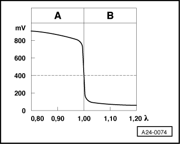
Note on display zone 2:
-
◆ The voltage signal "rich mixture (low level of residual oxygen)" is approx. 0.7...1.0 V.
-
◆ The voltage signal "lean mixture (high level of residual oxygen)" is approx. 0.0...0.3 V.
-
◆ When changing from "rich" to "lean" and back again (λ = 1.0) the voltage jump will change from 0.7...1.0 V to 0.0...0.3 V or back again.
-
◆ Due to the steep voltage jumps the Lambda control cannot keep the ideal mixture composition λ = 1.0 constant. The control fluctuates constantly between conditions "slightly too lean" and "slightly too rich".
-
◆ The displayed value must temporarily drop below 0.3 V and exceed 0.6 V. Displayed values below 0.45 V signifies lean, above 0.45 V rich.
|