seat Workshop Repair Guides

SEAT Workshop Service and Repair Manuals

Measured value blocks > < Final control diagnosis
Motronic injection and ignition system (4-Cyl.)
Final control diagnosis
Performing final control diagnosis

The final control diagnosis activates the following components in the stated sequence:

1. Injector, cylinder 1 -N30

2. Injector, cylinder 2 -N31

3. Injector, cylinder 3 -N32

4. Injector, cylinder 4 -N33

5. Solenoid valve 1 for activated charcoal filter -N80

6. Secondary air inlet valve -N112

7. Secondary air pump relay -J299

8. Charge pressure control solenoid valve -N75

Special tools, workshop equipment, testers, measuring instruments and auxiliary items required

  • ◆ Fault reader V.A.G 1551 or vehicle system tester V.A.G 1552 with cable V.A.G 1551/3
  • ◆ Test box V.A.G 1598/22
  • ◆ Adapter set V.A.G 1594
  • ◆ Hand multimeter V.A.G 1526 or multimeter V.A.G 1715
  • ◆ Diode test lamp V.A.G 1527
  • ◆ Current flow diagram

Test conditions

  • ● The fuses 4, 13 and 14 must be OK.
  • ● The fuse for the secondary air pump relay must be OK.

Notes:

  • ◆ The final control diagnosis can only be carried out if the engine is stationary and ignition switched on.
  • ◆ The final control diagnosis will be broken off if the engine is started or a rotational impulse is recognised.
  • ◆ During the final control diagnosis the individual final controls will be activated until advancing to the next final control by pressing the ⇒ button.
  • ◆ The final controls are checked acoustically or by touching.
  • ◆ If it is necessary to repeat the final control diagnosis, without first running the engine briefly, switch the ignition off for approx. 2 seconds.
  • ◆ The electric fuel pump will run during the complete final control diagnosis.
  • ◆ The final control diagnosis will be aborted after 10 minutes.

Work sequence

  • ‒ Connect the fault reader V.A.G 1551 (V.A.G 1552). Then switch ignition on and select engine control unit with the "Address word" 01.
    (Connecting fault reader and selecting engine control unit .)
 
→ Indicated on display:
Rapid data transfer    HELP
Select function XX
  • ‒ Operate fault reader taking into account the information on the display:
  • ‒ Press keys 0 and 3 for the function "Final control diagnosis".
 
→ Indicated on display:
Rapid data transfer    Q
03 Final control diagnosis

Activate injectors (N30...N33):

  • ‒ Confirm input with Q key.
 
→ Indicated on display:
Final control diagnosis    ⇒
Injector cylinder 1 -N30

Note:

The fuel pump must run and the flow noise must be distinctly audible at the fuel pressure regulator. If the fuel pump does not run, check activation.

=> Repair group 20; Removing and installing parts of the fuel system; Checking fuel pump

  • ‒ Open the throttle valve. As soon as the idling switch opens, the number 1 Cyl. injector will click 5 times.
  • ‒ Press the ⇒key each time to advance to the next injector (advancing is also possible without testing each individual injector).
  • ‒ All injectors can be checked one after the other in this way.

If one of the injectors is not activated (does not click):

  • ‒ Checking injectors => Page 24-64.

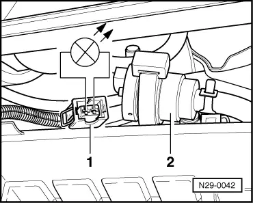
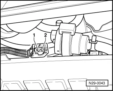
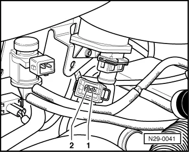
Activating activated charcoal filter solenoid valve 1 (N80):

  • ‒ Press ⇒key.
 
→ Indicated on display:
Final control diagnosis    ⇒
Activ. charcoal filter solenoid valve 1    -N80
  • The activated charcoal filter solenoid valve 1 must click until the next final control is activated by pressing ⇒key.

If the solenoid valve does not click:

 
N29-0042
  • ‒ → Pull connector -1- off solenoid valve -2- and connect diode test lamp V.A.G 1527 with aux. cables from V.A.G 1594 to disconnected connector.
        The LED must flash

LED flashes:

  • ‒ Renew solenoid valve.

=> Repair group 20; Activated charcoal filter system; Removing and installing parts of activated charcoal filter system

LED does not flash:

 
N29-0043
  • ‒ → Connect diode test lamp V.A.G 1527 to disconnected connector contact 1 and earth using auxiliary cables from V.A.G 1594.
        The LED must light up.

LED does not light up:

  • ‒ Check wire between 2 pin connector contact 1 and fuel pump relay (J17) for open circuit using current flow diagram.
        Wire resistance: max. 1.5 ω

LED lights up:

  • ‒ Switch off ignition.
 
N24-0810
  • ‒ → Connect test box V.A.G 1598/22 to control unit wiring harness.

 
N29-0043
  • ‒ → Check wire between test box socket 15+2 pin connector contact 2 for open circuit using current flow diagram.
        Wire resistance: max. 1.5 ω
  • ‒ Additionally check wire for short to battery positive and earth.
        Specification: ∞ω

If no fault in wire is detected:

  • ‒ Renew engine electronics control unit => Page 24-106.

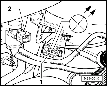
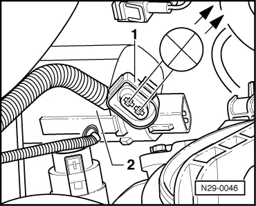
Activating secondary air inlet valve (N112):

  • ‒ Press ⇒key.
 
→ Indicated on display:
Final control diagnosis    ⇒
Secondary air inlet valve -N112
  • The secondary air inlet valve must click until the next final control element is activated by pressing the ⇒ key.
 
N29-0040

If the secondary air inlet valve does not click:

  • ‒ → Pull 2 pin connector off valve and connect diode test lamp V.A.G 1527 with aux. cables from V.A.G 1594 to disconnected connector.
        The LED must flash

LED flashes:

  • ‒ Replace secondary air inlet valve:

=> Repair group 26; Secondary air system; Removing and installing parts of secondary air system

 
N29-0041

LED does not flash:

  • ‒ → Connect diode test lamp V.A.G 1527 to disconnected connector contact 1 and earth using auxiliary cables from V.A.G 1594.
        The LED must light up.

LED does not light up:

  • ‒ Check wire between 2 pin connector contact 1 and fuel pump relay (J17) for open circuit using current flow diagram.
        Wire resistance: max. 1.5 ω
 
N24-0810

LED lights up:

  • ‒ Switch off ignition.
  • ‒ → Connect test box V.A.G 1598/22 to control unit wiring harness.

 
N29-0041
  • ‒ → Check wire between test box socket 33+2 pin connector contact 2 for open circuit using current flow diagram.
        Wire resistance: Max. 1.5 ω
  • ‒ Additionally check wire for short to battery positive and earth.
        Specification: ∞ω

If no fault in wire is detected:

  • ‒ Renew engine electronics control unit => Page 24-106.

Activating secondary air pump relay (J299):

  • ‒ Press ⇒key.
 
→ Indicated on display:
Final control diagnosis    ⇒
Secondary air pump relay -J299
  • The secondary air pump relay (J299) activates the secondary air pump motor (V101) which runs at intervals until the final control diagnosis is terminated by pressing the ⇒ key.

If the secondary air pump motor (V101) does not run at intervals:

 
N29-0046
  • ‒ → Pull 2 pin connector off secondary air pump and connect diode test lamp V.A.G 1527 with aux. cables from V.A.G 1594 to disconnected connector.
        LED must flash

LED flashes:

  • ‒ Renew secondary air pump:

=> Repair group 26; Secondary air system; Removing and installing parts of secondary air system

LED does not flash:

  • ‒ Connect diode test lamp V.A.G 1527 to disconnected connector contact 2 and earth using auxiliary cables from V.A.G 1594.
        The LED must flash

LED does not flash:

  • ‒ Check wire for open circuit between 2 pin connector contact 2 and secondary air pump relay using current flow diagram..
        Wire resistance: max. 1.5 ω

LED flashes:

  • ‒ Check wire for open circuit between 2 pin connector contact 1 and earth using current flow diagram.
        Wire resistance: max. 1.5 ω

If no fault in wire is detected:

  • ‒ Switch off ignition.
 
N24-0810
  • ‒ → Connect test box V.A.G 1598/22 to control unit wiring harness.
  • ‒ Check wire for open circuit between test box socket 30 and secondary air pump relay using current flow diagram.
        Wire resistance: max. 1.5 ω

If no fault in wire is detected:

  • ‒ Check voltage supply for secondary air pump relay using current flow diagram:

=> Electrical system; Repair group 90

Is the voltage supply and activation OK:

  • ‒ Renew engine electronics control unit => Page 24-106.

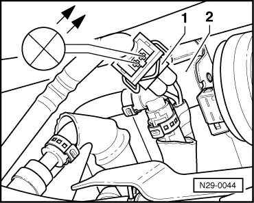
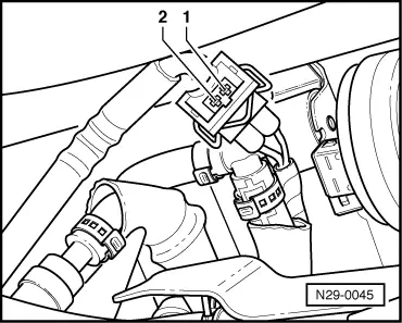
Activating charge pressure limitation solenoid valve (N75):

  • ‒ Press ⇒key.
 
→ Indicated on display:
Final control diagnosis    ⇒
Charge pressure control solenoid valve -N75
  • The solenoid valve must click.

Note:

The clicking of the valve is difficult to hear and is therefore best checked by touch.

If the solenoid valve does not click:

 
N29-0044
  • ‒ → Pull connector -1- off solenoid valve -2- and connect diode test lamp V.A.G 1527 with aux. cables from V.A.G 1594 to disconnected connector.
        The LED must flash

LED flashes:

  • ‒ Renew solenoid valve.

=> Repair group 21; Charge air system with turbocharger; Turbocharging overview

LED does not flash:

 
N29-0045
  • ‒ → Connect diode test lamp V.A.G 1527 to disconnected connector contact 1 and earth using auxiliary cables from V.A.G 1594.
        The LED must light up.

LED does not light up:

  • ‒ Check wire between 2 pin connector contact 1 and fuel pump relay (J17) for open circuit using current flow diagram.
        Wire resistance: max. 1.5 ω

LED lights up:

  • ‒ Switch off ignition.
 
N24-0810
  • ‒ → Connect test box V.A.G 1598/22 to control unit wiring harness.
 
N29-0045
  • ‒ → Check wire between test box socket 64+2 pin connector contact 2 for open circuit using current flow diagram.
        Wire resistance: max. 1.5 ω
  • ‒ Additionally check wire for short to battery positive and earth.
        Specification: ∞ω

If no fault in wire is detected:

  • ‒ Renew engine electronics control unit => Page 24-106.
  • ‒ Press ⇒key.
 
→ Indicated on display:
Rapid data transfer    HELP
Select function XX
  • ‒ Press keys 0 and 6 for the function "End output" and confirm entry with the Q key.
  • ‒ Switch off ignition.

Note:

Switch off ignition after completion of the final control diagnosis. If the ignition is not switched off before attempting to restart the engine, the engine will not start, as the injectors and the ignition transformer will not be activated.

Measured value blocks > < Final control diagnosis