seat Workshop Repair Guides

SEAT Workshop Service and Repair Manuals

Ignition system, glow plug system > < Self diagnosis
Simos injection and ignition system
Checking intake air temperature sender

Special tools, testers and auxiliary items

  • ◆ Fault reader V.A.G 1551 or vehicle system tester V.A.G 1552 with cable V.A.G 1551/3
  • ◆ Test box V.A.G 1598/18
  • ◆ Hand multimeter V.A.G 1526 or multimeter V.A.G 1715
  • ◆ Adapter set V.A.G 1594
  • ◆ Current flow diagram
  • ◆ Chilling spray (commercially available)

Test sequence

  • ‒ Connect the fault reader V.A.G 1551 (V.A.G 1552) and with ignition switched on select engine electronics control unit with the "Address word" 01.
    (Connecting fault reader and selecting engine electronics control unit .)
 
→ Indicated on display:
Rapid data transfer    HELP
Select function XX
  • ‒ Press keys 0 and 8 for the function "Read measured value block" and confirm entry with Q key.
 
→ Indicated on display:
Read measured value block    HELP
Input display group number XX
  • ‒ Press keys 0 and 2 for "Display group number 02" and confirm entry with Q key.
 
→ Indicated on display:
(1...4 = Display zones)
Read measured value block 2    ⇒
    1    2    3    4

Functional check of sender

  • ‒ Read off intake air temperature value in display zone 4.

Display

Cause

Continuation of check

5 °C

Open circuit or short to positive

=> Page 24-60

Short to earth

Approx. ambient temperature1)

---

=> Page 24-62

    1)    If a temperature is displayed which deviates greatly from the ambient temperature of the sender, check sender wiring for transfer resistances.

 
N24-0266

Continuation of check when display = approx. 5 °C:

  • ‒ Press the ⇒key.
  • ‒ Press keys 0 and 6 for the "End data transfer" function and confirm input with the Q key.
  • ‒ Switch off ignition.
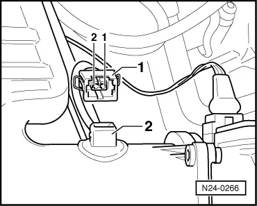
  • ‒ → Pull 2 pin connector -1- off intake air temperature sender (G42) -2-.
  • ‒ Check sender resistance.
        Specification => Page 24-18, Fig. 1

If the specification is not obtained:

  • ‒ Renew intake air temperature sender (G42)
    , item 3.

If the specification is attained:

  • ‒ Remove dash panel insert.

=> Electrical system; Repair group 90

 
N24-0219
  • ‒ → Connect test box V.A.G 1598/18 to control unit wiring loom.
  • ‒ Check wire between test box socket 37and 2 pin connector contact 1 as well as socket 29 and contact 2 for open circuit according to current flow diagram.
        Wire resistance: max. 1.5 ω
  • ‒ Check wire between control unit connector and 2 pin connector contact 2 for short to wire contact 1 as well as to vehicle earth, according to current flow diagram.
        Contact 2+socket 37
        Specification: ∞ω
  • ‒ Check wiring additionally for short circuit to battery positive.
        Specification: ∞ω

If no fault in wire is detected and the intake air temperature sender is OK:

  • ‒ Renew Simos control unit (J361)
    , item 14.

Continuation of check when display = ambient temperature:

 
N24-0267
  • ‒ → Remove intake air temperature sender (connector remains connected).
  • ‒ Note intake air temperature value in display zone 4.
  • ‒ Spray sender with commercial chilling agent whilst observing the temperature value. The temperature value must
        decrease.
  • ‒ Press the ⇒key.
  • ‒ Press keys 0 and 6 for the "End data transfer" function and confirm input with the Q key.

Ignition system, glow plug system > < Self diagnosis